Hi darkfenriz,
Those who tell you it is not a problem are not considering dynamic waveform change that causes powerful momentary crossover/loudspeaker back-EMF induced current flow through that choke that is not related to signal input.
There is no problem only if you look at the difference with steady sinewaves in time isolation !.
Cheers ........ Graham.
Hallo
I didn't mean steady sine- it would be naive.
I just think, that inductace of output choke togrther with load impedance are of so low Q, that I wouldn't care. Passive crossovers are much worse.
I didn't mean steady sine- it would be naive.
I just think, that inductace of output choke togrther with load impedance are of so low Q, that I wouldn't care. Passive crossovers are much worse.
If only digital source material is used, the question that comes up is "Is the effect audible with bandlimited source material?". One interesting feature of LTSpice that I haven't tried yet is its ability to use a WAV file as input, and produce a WAV file at the output. Seems like these scenarios could be investigated in the simulator using actual music as input and output.
Next weekend I think I'll write a small utility to convert stereo WAV files to mono and try some of this stuff out. My main source material for my stereo is from my music server to a Squeezebox 2 / Benchmark DAC combination. Seems like this would work well for listening to the resulting WAVs on headphones.
Next weekend I think I'll write a small utility to convert stereo WAV files to mono and try some of this stuff out. My main source material for my stereo is from my music server to a Squeezebox 2 / Benchmark DAC combination. Seems like this would work well for listening to the resulting WAVs on headphones.
Hi Andy,
I would really look forwards to hearing your results from that.
Good source quality you have there.
Cheers ........ Graham.
I would really look forwards to hearing your results from that.
Good source quality you have there.
Cheers ........ Graham.
Hi darkfenriz,
Thanks for that question.
Further thought.
The most powerful back-EMFs are dynamically induced and do not get the chance to become 'steady linear' due to interaction between on-going audio drive and multiple differently energised time constants within a composite system.
Hi Mauro,
I went through your thread.
I had come across it before, but did not take interest because it was a 'chip' amplifier.
I wanted to carry on with discreet construction that would not need to have any current limiting arrangements cutting in because of impedance dips on 4 ohm loudspeaker systems.
Very interesting circuit though. Then you improved it.
At a later date you check the damping level/phase characteristic via reverse injection, and your prior series of improvements are shown to have been worthwhile.
You cannot get better than that !
Conclusion: Both the modifications, and the reverse injection test are validated.
Cheers .......... Graham.
mauropenasa said:If you want see the ameliorations that have introduced creditable to your test...
http://www.diyaudio.com/forums/showthread.php?postid=683428#post683428
Ciao
Mauro
Mauro
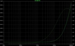
Here's the output impedance of a VERY HEAVY feedback amp I've posted in another thread.
Attachments
Hi Jorge,
Can we see the circuit please ?
You could get this with almost any amplifier and a series 0.2 ohm output resistor !!!
Cheers ........... Graham.
Can we see the circuit please ?
You could get this with almost any amplifier and a series 0.2 ohm output resistor !!!
Cheers ........... Graham.
he he, Jorge,
I don't will invaded this thread with the analyses of my circuits.
I have done a reference to my work to show ( with the facts ) to Graham that I have not prejudices on the theories that find in this forum. If it works am pleased about applying it ( and share it ).
The only comment is that as you have already said, is a lot of different to trace a graph on "virtual circuits" by the verify that the result is "musical".
In my case, I have worked on a circuit already "musical" and that know from a lot of years...
Ciao
Mauro
Graham Maynard said:Hi Jorge,
Can we see the circuit please ?
You could get this with almost any amplifier and a series 0.2 ohm output resistor !!!
Cheers ........... Graham.
Graham
That's exactly what I've done.
So much arguments when a resistor will change one amp's spec to one's liking...
Regards,
Jorge
Graham Maynard said:Hi Michael,
(Hopefully this feedback not causing instability.)
Hi Graham,
in a response to your post
#141
Yes I suggested that we could instead of using the phrase "back EMF" use the phrase "reactive loads", eg. when current and voltage is out of phase, but no big deal here.
Yes of course a loudspeaker element have a resistive part of it's frequency response too.
But this frequency area looking at the paper to be resistive can still be consisting of reactive parts as much as you would say the back EMF the same frequency area would be.
Here's a link to a Scan Speak tweeter D2008 , we can now see that the capacitive part for this particular tweeter is ranging from around 800 Hz to 4 kHz were it's resistive part is located.
Back to the reactive part at a resistive frequency area, the 4 kHz picked from above mentioned tweeter, I would say the inherent real electrical inductance is exsisting all the way from 0 Hz, but it's just that it is starting to be visible on the frequency chart first above 4 kHz because mechanical reactiv components (both capacitive and inductive = which have f0 were the resonance frecuency is, combined of course with the electrical resistivity and inductance etc.)parts are swamping out the inherent electrical inductance out of visibility on the paper, not to forget also the electrical resistivity in the VC.
So at 4 kHz there's still a reactive component even if it's on paper a fairly resistive area, and even if you perhaps would say back EMF.
Actually I asked you earlier regarding the resistive frequency range of a loudspeaker element in another post in the thread The many faces of distortion post #356
Graham Maynard said:
Hi Michael,Ultinma Thule said:Hi Graham,
Another questions, would you say there are any problem with loudspeaker EMF and some amplifiers:
* at impedance peaks and impedance dips?
* at falling impedance area of loudspeakers impedance with rising frequency?
Would you say loudspeaker EMF is a problem for the second input node in all amplifier, eg. the feedback node, and is it the only or partial biggest problem, or what is the partial biggest problem from your standpoint?
Regards Michael
Any amplifier that has low amounts of quadrature damping can be bothered by some loudspeakers.
I'm only passing on obsevations, so I cannot say for sure exactly what will be a triggering factor.
Voltage amplifier current energisation of a composite loudspeaker changes considerably during the first cycle of any musically changing input as the loudspeaker builds up its back-EMF, and by the time that back-EMF has developed the music has moved on. If the amplifier correction is in quadrature I wonder where this leaves reproduction when the loudspeaker's electrical response is itself not in phase.
Cheers ........ Graham.
Your writings left a question, especially the last one from your post quoted above were you talk about the quadratur damping.
Or actually, I would say yes I understand your point in a way, but the resistive frequeny area of a loudspeaker element is not a problem as the amplifier can't see any currents out of phase here.
There are some small issues I actually am pondering over regarding loudspeaker elements, but I guess I have to make a small research some time in the furture when I got the right time.
You also discuss what happens to an amplifier subject to back-EMF, and then conclude that there is no real problem.
But what happens when capacitive devices and stabilisation components are enclosed within a global NFB loop ?
Answer;- the amplifier's output terminal becomes inductive = reactive; ie. not passive.
I'm not sure what you mean with capacitive components within a global NFB, may I guess you mean such components as the Miller cap added to the VAS transistor and the Zobel network at amplifier output etc?
If that's what you meant I don't think it's a problem if the amplifier output phase is small at 20 kHz, I would make a general statement that my belive has always been leaned to extremly fast amplifiers especially when the amplifier is wrapped around with a global FB.
Other capacitive components are the speaker cables and the for the highest capacitive frequency ranges for a loudspeaker, the tweeter, as for the above SS tweeter example is capacitive below 4 kHz, which I wont consider as problematical high frequency.
How much is the phase for any deascent amplifier at 4 kHz, not much to ponder about I guess.
But Graham, I see you have a point when talking about back EMF, what a small addition of distortion added from external non resistive non linear loads can do in a FB amplifier, but certain criteries is to be fullfilled, or actually avoided if we want a good sounding amplifier.
Yes, shortly any kind of reactive/non linear load will do this, but even if we would add just a simple inductor to the amplifiers output we shall not forget that even this is a fairly unlinear component too with quadratur distortion, eg. B/H hysteresis, especially inductors with a core.Amplifier output terminal current flow is modified by loudspeaker system generated back-EMF. Loudspeaker sytem back-EMF comprises a complex mix of crossover component back-EMFs and driver/cabinet induced back-EMFs.
Leading error voltage, the same as lagging current eg. the same as the the correcting current is arriving too late: yes, for a tweeter alone for an example it's below 4 kHz as for the example tweeter mentioned above, but for a less well designed amplifier this is for sure a problem.. but it must be a really lousy amplifier?!Changes in loudspeaker current flow can develop a leading error voltage across the amplifier's internal inductance, and this error voltage is unavoidably in series with the NFB loop controlled output.
Capacitors compared to inductors are more linear even if they have too a so called dielectrical hysteresis, so a Zobel at the output of the amplifier is in many cases the capasitive component/network which are exposed to the highest frequency seen at the amplifiers output.
What is left is the nonlinearities found in the speaker elements, and these are worst at high listening levels, at normal listening level (which may be quite subjective what it means) it's a smaller problem however.
BTW, I think that an GFB amplifier with lower damping factor is more prone to the back EMF arteffects than a high damping amplifier, if all else equal, especially slow one's.
So far no instabilities! 🙂
Cheers Michael
janneman said:Why are you always trying to cram long strings of terms into seemingly endless statements that are so difficult to decipher? It is difficult enough without the language barrier that must be formidable for many here. Don't you WANT us to understand you?
My experience is that when people have problems understanding a point, they tend to write in such a "sophisticated" way to hide away their lack of understanding.
I am still unclear what "back EMF" is, quite frankly. If it is about voltage and current out of phase (thus, the lagging one "resisting" the leading one), it is no difference from what we have in a capacitor, or an inductor. just exactly sets a speaker apart from a capacitor/inductor in this perspective?
to me, this is a problem existed just for the purpose to have a solution.
Hi Jorge,
You know I have suggested trying a 0.22 ohm resistor when there are amplifier/loudspeaker interface problems.
However, irrespectively of stated feedback level and/or phase response, not everyone 'likes', or chooses, or is in a position where they can use, an amplifier with such a low damping factor.
This is why technical *discussions* continue. Hopefully properly positive discussions.
Hi Michael,
I was about to drop out of this thread.
Brilliant ! A technical discussion.
We are agreed - there's always more than one way of viewing a problem.
Another reason I prefer to keep back-EMF and reactivity separate, is because loudspeaker generated back-EMF can be reactively delayed on its way back to the amplifier. The mechanisms are different.
Jan pointed out my inconsistency when I mentioned 'quadrature damping' in answer to your question, I trust you saw my rewrite of that sentence.
Yes I did leave another question; - I have not even tried to think that one out for myself yet ! I might not either, for if you make the amplifier fully competent it becomes irrelevent.
Capacitive components;- Miller, device junctions etc.
You can still have a NFB flattened forward amplifying phase response without having a flat reverse phase response coherently coping with back-EMF.
( I'm sure Mauro will agree on this.)
It does not matter how perfect the loudspeaker is from a response or linearity point of view, you can still 'hear' when the amplifier is not right.
Inductors; yes cores can be a problem, but inductor non-linearity apart, it is voltage leading the current flow that is the problem.
Amplifier NFB control is voltage sensed but current based, so any series inductance between loudspeaker back-EMF and a high damping factor amplifier will allow sudden leading voltage error development at the loudspeaker terminal wrt amplifier. Fractional only, but still audible, and still able to transfer from mid section to tweeter. This is why I suggested simulation. Actually I think it likely an amplitude/phase plot will show where to look.
You say 'must be a lousy amplifier' for problems to show.
Back to my question of the definition of a good amplifier.
You cannot claim an amplifier is good by frequency response, stability, slew and thd alone; you *must* look at its reverse characteristics (back-EMF controlling capabilities) too, or listen and improve empirically over a long period.
The fastest relative current changes in an amplifier arise due to NFB loop sensing; often through the VAS Miller compensation capacitor where fitted.
Your last 'BTW' statement. I'm not sure what you intend to say there.
Whether any amplifier is more prone to back-EMF is related to quiescent current, damping factor, and the phase angle of its damping response with frequency.
ie. a high current, low damping factor amplifier that provides phase coherent damping can produced lesser levels of phase shifted voltage error than one with low current and high damping but fitted with necessary stability components which, when enclosed by the closed global loop, render the damping response inductive at audio frequencies.
Thanks for your sensible posting.
Hi tlf9999,
I don't have to put up with such snide comments all the time.
It is positive contributions you should be making, not provocative ones.
If you cannot understand, it is neither my fault nor my responsibility.
Goodbye.............. Graham.
tlf9999, what are you doing?,dont you get anything my friend
these people try to solve a problem and they dont know how
the last thing they want is tlf9999 telling them they know nothing
cheers
these people try to solve a problem and they dont know how
the last thing they want is tlf9999 telling them they know nothing
cheers
mastertech, maybe you are right. In the end, people do have the right to waste their time and insist on being wrong, don't they?
Cheers.
Cheers.
Back EMF is real !
Hi tfl9999 and others who have any doubts.
You might have come across back EMF in your physics class or at the engineering school.
Take a galvanometer ( preferably a sensitive one - say 50 micro Amp sensitivity for full scale) and pass a current to get full scale deflection. Then remove the signal current ( leave the meter terminals open ). The pointer will fall back to zero reasonably fast. Now pass the current again to get full deflection and then 'short' the meter's two leads. You will find the pointer dropping down to zero rather slowly . That is because the back emf generated by the coil is now causing a reverse current that damps the movement .
The same thing happens in a speaker coil . This is particularly effective when the incoming signal drops to zero and the cone continues to move beyond the zero ( rest ) position. Sine waves particularly will cause cones to move fastest ( slew rate ) when they are crossing the zero position . So the cones need help to stop - mechanically and electrically. Most often the electrical circuit can do most of the controlling.
So back EMF is a voltage generated by the voice coil when it moves in a magnetic field. It is very small in amplitude compared to the usual musical signals driving the speaker. The resultant current - when the leads are shorted or go to a low impedance amplifier output - is responsible for the positional damping of the cone. This is obviously significant when the musical signals drop to zero.
I hope this makes things clear.
Cheers.
Hi Ashok,
Thanx for clarifying the statement of Back Emf to others...
but it really amazed me very much that concepts like back EMF is very simple and basic in nature and these people are still unaware of that concept...and having some difficulty to accept that "BACK EMF" really exists in reality....
cheers,
K a n w a r
Workhorse said:but it really amazed me very much that concepts like back EMF is very simple and basic in nature and these people are still unaware of that concept...
I don't really think it's a lack of awareness. Rather, most people know that the back EMF increases the loudspeaker impedance above that of its series resistance and inductance. Further, a good many know that an increase in load impedance to a power amplifier will decrease its distortion. So it's natural that people would find the claims that back EMF does all kinds of evil things to be lacking in credibility.
The issue of speaker nonlinearity sometimes gets thrown it to support the claims, but that's been addressed by various IM tests and simulations by applying an amp input at a frequency f1, while injecting a signal at its output at a frequency f2 and looking at the intermods. There were no surprises here, with the distortion generally being reduced by the amount of feedback, even though the loop gain has -90 degree phase shift at the frequencies considered.
There have been further assertions that a resistive output impedance improves performance even if it requires making the impedance higher than that of a typical feedback amplifier. It's not clear to me the specific nature of the claimed improvement, but given some clarification as to the claimed improvement, it would be interesting to test it in an objective way.
tlf9999 said:
I am still unclear what "back EMF" is, quite frankly.
From the above post , it clearly denotes that this guy is really unaware of the fact ,what is known as Back EMF...as it seems quite reasonably by reading that post....
andy_c said:
I don't really think it's a lack of awareness.
If these people cannot accept that Back EMF does exist and have an effect on amplifier than i think giving comments on Mr.Maynard research by these guys is simply not a good manner....
Hi Graham Maynard,
kindly carry on your research because it is yeilding some good results which could be of great help in amp designing....
regards,
K a n w a r
Hi all,
Sorry to butt in, but I have a few questions regarding back EMF.
I’m sorry if these questions have already been addressed elsewhere in the thread, but I did not want to look through all the posts – here goes.
1 When simulating the back EMF in a simulator, I think it is required to input some sort of acoustic system since it must be the movement of the speaker cone + voicecoil that generates the back EMF (Like on any magnetically helped moving devise e.g. like a motor) Is the correct?
2 The EMF adhering from the movement must be bigger in large drivers (Large magnet + coil) or am I mistaken?
3 Looking at active speakers, there is less need to worry about this, since the individual speakers will not disturb the others (There is no connection) - ?
\Jens
- Status
- Not open for further replies.
- Home
- Amplifiers
- Solid State
- Back EMF - some considerations