Wasn't there a law of conservation of mass?
gain_mass := fat(icecream) + sugar(Coke^2) - sqrt(drillwork) 😎
What a beast.... ...settled the switching frequency around 310kHz... to care about all the details I described prviously and at least it seems to work OK now. I had quite some struggle during my small signal measurements. It seems to be possible to kill the IRS20954 if the comparator stage is delivering disturbed signals. I killed the IRS20954 two times during measuring the small signals. In both cases the power stage remained perfectly fine, but the IRS20954 was dead. The lower driver stage was defect, short between LO & VCC. I do not like this sort of failures... causing some doubts regarding reliability.
Hm, what else do I not like?
The selfresonant topology is nice and simple. But in case of heavy clipping or short disturbances it tends to lock up. A huge capacitor for VS-VB is improving but not 100% curing the clipping behaviour, right now I am using 10uF.
...thinking about the second chanel. With the experience from above I am not really willing just to reproduce a second full bridge.
I am thinking about a different PWM system and also I am thinking about the IRS20955. It has a longer blanking for the OC detection, 450ns instead of 200ns.
Furtheron it is also offered in dual inline package, which is much more repair-friendly. Removing defect SMDs is always stressing the PCB and killing the entire set up already after 5 defects... So I prefer the dual in line for the R&D work.
ChocoHolic said:The boards are about 98mm x 82mm. Eagle light does not allow components beyond 100 x 82.
Normal pricing for 20 pieces would have been about USD 250. Well, a local friend who knows them helped me ...here it's all about personal relations... and I got them for a real friendship price... 😉
this price is wrong, 250RMB-300RMB is right
rg
fumac
fumac said:
this price is wrong, 250RMB-300RMB is right
rg
fumac
You are confirming my privat opinion.
Is your comment a binding offer? 😀
ChocoHolic said:The selfresonant topology is nice and simple. But in case of heavy clipping or short disturbances it tends to lock up.
I've had similar experiences with much lower power self oscillating topologies. Heavy clipping and transients much faster than normal audio signals caused the output stage to stick to one rail and
 goes the silicon... and sometimes the PCB pads soldered to the IC pins.
ChocoHolic said:Furtheron it is also offered in dual inline package, which is much more repair-friendly. Removing defect SMDs is always stressing the PCB and killing the entire set up already after 5 defects... So I prefer the dual in line for the R&D work.
If you don't have or have access to a hot air rework station removal of SMDs without damaging the board can be rather difficult. 5 repairs on the same spot is really good without hot air! With proper hot tools I've been able to replace 80 pin micros upwards of 10 times without any visible damage to the PCB.
fumac said:250RMB-300RMB is right
fumac, are you saying you can get 20 of Chocoholic's boards made for about 40USD?!?!
Is this a standard price? If so, what manufacturer are you using?
i'm not pcb saler🙂🙂
my double side pcb , 2Oz, 100mmx100mm, and i want 16 pcs demo , i just pay 300RMB 🙂
the pcb is made in panyu, guangzhou ,china
the boss is my good friend. i pay 300rmb,
and he invite me to have dinner🙂🙂🙂
close to u 🙂
i'm living in guangzhou and foshan, close to u too
if need, mailme or take my skypy fumac1@gmail.com
and if u want to test something, u can goto my lab,
rg fumac
Hi Fumac !
This is sounding quite friendly!!
🙂 🙂 🙂 🙂 🙂
It could happen that I'll contact you soon...
I am thinking about new PCBs of my next gen Class D Rookie. And a good audio test lab is also quite promising! ...compared to my cheapy 2-channel USB scope...
This is sounding quite friendly!!
🙂 🙂 🙂 🙂 🙂
It could happen that I'll contact you soon...
I am thinking about new PCBs of my next gen Class D Rookie. And a good audio test lab is also quite promising! ...compared to my cheapy 2-channel USB scope...
infact, chinese is friendly to anyone,
i make many foreign friends here, include englan, italy, span,usa,...
they r kind as u🙂
but we r not very well in english, so we will make some mistake sometimes
i think this is not a wall to stop friend
,🙂
i have goout from last company, and i build my personal lab myself,
a personal lab is my dream from childhood, WE can design any thing that we interet in.
and the lab is welcome any body who have intereting.
RG
fumac
Two more points for discussion:
1.
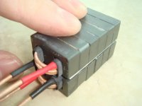
My current output filter consists of coupled inductors 2x4.5uH acting like 1x18uH, 2x1.5uF to ground and a 5 Ohms+4.7 uF filter damping circuit....
It provides less than 2db ripple and f3 above 30kHz at all normal loads. Means no load ... to 4 Ohms.
The remaining HF output ripple is about 2x1.5Vpp if the full bridge runs at +/-55V.
If I measure the impedance of my Dynaudio speakers, I can find a 5.4 Ohms impedance with 12° inductive phase shift at 310 kHz. This means I would have something like 0.7W HF ripple losses in the tweeter. This will probably not immediately kill the tweeter, but it is already an unpleasant 'bias heating'....
What are your expiriences in this regard?
2. In general if we supperimpose two signals with slightly different frequencies this will add up to an signal with an envelope that shows an beat of f1-f2.
If we imagine class D amplifiers... left chanel running at 314kHz, right chanel running at 310kHz... then i am wondering if this could lead to an audiable f1-f2 beat...
Any experiences with that?
1.
My current output filter consists of coupled inductors 2x4.5uH acting like 1x18uH, 2x1.5uF to ground and a 5 Ohms+4.7 uF filter damping circuit....
It provides less than 2db ripple and f3 above 30kHz at all normal loads. Means no load ... to 4 Ohms.
The remaining HF output ripple is about 2x1.5Vpp if the full bridge runs at +/-55V.
If I measure the impedance of my Dynaudio speakers, I can find a 5.4 Ohms impedance with 12° inductive phase shift at 310 kHz. This means I would have something like 0.7W HF ripple losses in the tweeter. This will probably not immediately kill the tweeter, but it is already an unpleasant 'bias heating'....
What are your expiriences in this regard?
2. In general if we supperimpose two signals with slightly different frequencies this will add up to an signal with an envelope that shows an beat of f1-f2.
If we imagine class D amplifiers... left chanel running at 314kHz, right chanel running at 310kHz... then i am wondering if this could lead to an audiable f1-f2 beat...
Any experiences with that?
ChocoHolic said:If we imagine class D amplifiers... left chanel running at 314kHz, right chanel running at 310kHz... then i am wondering if this could lead to an audiable f1-f2 beat...
It sure can. How audible the beat frequency is depends on the extent of the interaction between the two circuits; physical separation, radiated immunity, susceptibility to EMI, power supply configuration, and wiring are some of the main points to consider.
ChocoHolic said:Two more points for discussion:
1.
My current output filter consists of coupled inductors 2x4.5uH acting like 1x18uH, 2x1.5uF to ground and a 5 Ohms+4.7 uF filter damping circuit....
It provides less than 2db ripple and f3 above 30kHz at all normal loads. Means no load ... to 4 Ohms.
The remaining HF output ripple is about 2x1.5Vpp if the full bridge runs at +/-55V.
If I measure the impedance of my Dynaudio speakers, I can find a 5.4 Ohms impedance with 12?inductive phase shift at 310 kHz. This means I would have something like 0.7W HF ripple losses in the tweeter. This will probably not immediately kill the tweeter, but it is already an unpleasant 'bias heating'....
What are your expiriences in this regard?
2. In general if we supperimpose two signals with slightly different frequencies this will add up to an signal with an envelope that shows an beat of f1-f2.
If we imagine class D amplifiers... left chanel running at 314kHz, right chanel running at 310kHz... then i am wondering if this could lead to an audiable f1-f2 beat...
Any experiences with that?
300k is hard to made a filter in 20-22k, i have test a 400W poweramp made by myfriend, use ti chips, runing at 300k about, the output ripple is about 3v P_P, this is y i turn up the freq, if 500k will have a lower output.
my amp running at 980k and 995K, i cant heard any noise from it, but i have turn one side to 1.05mhz , for save🙂
i'm afrad that the f1-f2 beat will come out sometimes.
rg
fumac
I simulated this with signal generators .... and.... urghs... hell ! It is quite audiable ! For me this looks like a clear NoGo for multi chanel class D with unsynchron modulation.
Hm, ...seems to be a big drawback of selfresonant topologies in general. Because I have no idea how to synchronize such systems. Do you?
I have to make up my mind regarding more traditional sawtooth or triangle modulations, which allow simple synchronization just by using the same triangle/sawtooth for all channels. Hm....
Which other modulation systems that offer easy synchronization would you recommend?
i think , u can try it just this way, u can drive up the freq of other channle,
i never heard any noise from the amps, even i asm they together,
Separate them , include Separate power.
RG
FUMAC
i never heard any noise from the amps, even i asm they together,
Separate them , include Separate power.
RG
FUMAC
It was not loud.
My set up was two signal generators.
One at 307kHz driving 0.4Vp in one speaker.
The second 312khz driving 0.4Vp in the second speaker.
My signal generators are not strong enough to drive higher levels into the 4 Ohms speaker. But already at this level which is about 17db less than what my 1kW amp would generate... I could already hear a slight beeping. I don't like....
Of course higher frequencies and lower power do help:
1. Lower power means lower rails, means less HF ripple.
2. Higher frequency reduces the HF ripple if the output filter remains settled to 30kHz.
3. At higher frequency the tweeter produces less sound.
4. At higher frequencies the f1-f2 is more likely to be above 20kHz and not audiable.
But I need the 1kW power. And increasing the switching frequency to 1MHz combined with +/-55V and 30A is not Rookie-like. In fact already at 310kHz my MosFets and the MosFet driver already show significant losses.
u r right
i have a damp working at 700Khz and +/-50V ,
if i btl it, the power is very high,
i use fets can working at 20A (one fet),
and i use a 1000w sw-power .
so the max power output is close to 800w.
but i'm not have a full test now, is busy this days.
i'm drawing a new pcb use 40A FET, can working at +-80V or +- 90V, is a test board for high power output .
but i think i will let it runing at 400-500k.
if mutichannel, 380k,430k,480k,530k, i think is ok,
rg
fumac
Music inside
😎
Just started my first listening tests. And yes you can hear music with that thing. More than just noise.
Not so bad until now....
I have to do more detailed listening and compare it vs my analogue bipolar Rookie.
Fumac,
I am quite curious to see your designs soon. 🙂
In fact I have no experience how much difference you need for the modulation frequency. Your proposal of 50kHz looks reasonable, but might depend on your topology. If you have fixed frequencies U might even put them closer, i.e. 30kHz steps. If you have frequency shifting topologies it might be more difficult to determine the required difference....
- Status
- Not open for further replies.
- Home
- Amplifiers
- Class D
- Babysteps of 1kW Class D Rookie Amp