R15? What's that? So if a resistor is absent upon inspection, was it absent prior to? (Gotta be philosophical).
Probably take me a couple days to get back up and try again.
Probably take me a couple days to get back up and try again.

Well, still having problems and at a dead end. I've gone over everything on this board for placement, value, operation, solder joints, etc.. and haven't found anything. I replaced Q1,2,T6 even though they tested fine. Powering up with light bulb, everything looks ok. No longer having any rail voltage offset. Switched out light bulb, and looked good on startup, went for a few seconds, until fuse blew on negative rail.
Is there anything I can probe with it powered by light bulb, or variac for troubleshooting?
Thanks,
Chris
Is there anything I can probe with it powered by light bulb, or variac for troubleshooting?
Thanks,
Chris
did you tested all surrounding components, what I wrote in #1936?
what value of fuses in rails? say that 2A5 is more than adequate
now, you can test FE itself, removing pcb from pucks (so no jeopardy of big nasty currents), first dialing Iq pot all the way CCW and shorting G to S for both pucks on pcb, to establish proper NFB loop for FE
but - first check ZD3 and ZD4 are they both alive
Yes tested all components in #1936, all fine. 2a5 fuse in each rail.
I'm not knowledgeable enough to test FE at this time. Give me a few days to get up to speed a bit, and then I can ask for more clarification.
Thanks
I'm not knowledgeable enough to test FE at this time. Give me a few days to get up to speed a bit, and then I can ask for more clarification.
Thanks
ZM,
Your annotated schematics are always super useful and a learning exercise as well! Please post if you have time. I’ve been toying with the idea of building a PoP or the XA252. I think I’ll just go for the big Kahuna XA252 as dedicated monoblocks. Will pm when I am ready…
Best,
Anand.
Your annotated schematics are always super useful and a learning exercise as well! Please post if you have time. I’ve been toying with the idea of building a PoP or the XA252. I think I’ll just go for the big Kahuna XA252 as dedicated monoblocks. Will pm when I am ready…
Best,
Anand.
ok, will post schm for FE testing, sans pucks, tonight
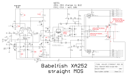
here it is - testing only FE
steps are - removing pucks from game , so no nasty surprises
establishing NFB loo ( broken without pucks in place) so FE is having all what's necessary to behave
Attachments
yeah, brainfart or double typo ...... typing on pic while already calculating next instance
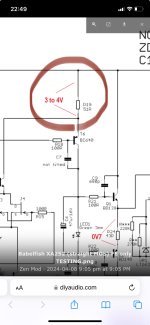
10 times less, so 300-400-500mV
thank you
edit ...... first I uploaded pic without voltage values
then wanted that too, so was sorta in a hurry while I still had time to edit post/replace uploaded file
10 times less, so 300-400-500mV
thank you
edit ...... first I uploaded pic without voltage values
then wanted that too, so was sorta in a hurry while I still had time to edit post/replace uploaded file
Ok, ran test as prescribed. I did use light bulb with rails at +-38v.
R7: 14.8v
R10: 1v17
R14: 0v663
R19: 0v605
R24: 1v41
Between r20-T7: 0v668
Between r9-T3: 0v668
R7: 14.8v
R10: 1v17
R14: 0v663
R19: 0v605
R24: 1v41
Between r20-T7: 0v668
Between r9-T3: 0v668
LED is common diffuse type, Green, so 1V9 across?
what voltage is at Q1 E, ref to GND?
recheck voltage E-B for both Q1 and Q2
what voltage is at Q1 E, ref to GND?
recheck voltage E-B for both Q1 and Q2
LED standard Wurth WL-TMRW
LED: 2v6 across
Q1 E ref to ground: 0v083
Q1 E to B: 0v59
Q2 E to B: 0v59
LED: 2v6 across
Q1 E ref to ground: 0v083
Q1 E to B: 0v59
Q2 E to B: 0v59
Ok Swapped out. Behaving better now:
LED: 1v95
Q1 E ref to round: 0v076
Q1 E to B: 0v62
Q2 E to B: 0v60
LED: 1v95
Q1 E ref to round: 0v076
Q1 E to B: 0v62
Q2 E to B: 0v60
so, it seems that everything is OK with FE now
while setup as is - can you check voltages across small smd resistors in biasing circ, practically voltage between positive rail and emiters of Q3, Q5, same as voltages between negative rail and emiters of Q4, Q8
that will tell is biasing circ operational
when that done, do not mount pucks yet, remove bridges you soldered form G to S of pucks , then with circ powered Off, check all resistors in between/around puck gates, meaning 10K R32,R33 and gate resistors R51, R52
it'll be cunning to dial Iq pot all the way CCW, preparing for full circuit testing afterwards
important note - pucks mounting - side with slit for screw goes looking at 0R56 group on pcb, side with hole for screw goes to down edge of pcb, speaker trace
Same voltage across Q3,5,4,8: 0v793
In circuit, R32+33 start at 6k and climb towards 10kohms. I checked them out of circuit earlier and they exhibited same, and were 10k when removed.
Yup, I know correct puck orientation, which was heeded originally.
So, next is to start on the startup procedure as you detailed pg 1. I will await your ok.
Thank You!!!!
what you have populated for R** and R***?
sum value needs to be in range of 121K (270K//220K), or one single 120K resistor in place of any of those
so, LT3092 works as 10uA through said resistor ( group)
now, if 10uA goes through 120K, gives 1V20
divided with (R28 + P2) (when P2 is all the way CCW, so 500R) goes to (1K5+500R)
goes to 1V20/2K=600uA
600uA through R29 and R30 (both 470R) gives 282mV
you have 0V793, saying that you have way too much programmed current thorough LT3092, in range of 0V793/40R=1.68mA
if powered like that, it'll give way too high OS Iq
- Home
- Amplifiers
- Pass Labs
- Babelfish XA252 / Babelfish XA252 SIT / Babelfish XA252 SET