

@sp33ls
read few first pages of https://www.diyaudio.com/community/threads/sissysit-r-3.371272/
actually setting the bias
one way is opto nested in between gates of output parts (as in SissySIT), other way is resistors nested in between gates of output parts (fed through CMirrors; as here, Babelfish XA252)
in both cases, precision CCS is crucial , as reference
Pa is using plain resistors for that but, hey, he is Papa; I'm just ZM Chicken
I'm ready, been waiting for this one a while. Guess I can go ahead and get transformers ordered.
Russellc
Russellc
Ring that bell 🔔 please? Ding dong!well, some of Greedy Boyz were just slightly more successful in twisting my hand to get them
I'm more than late/not actual with several Trade threads, and Babelfish XA252 is just one of them
in mid of solving some decent quantity of LT3092 (still going to be sole option for this amp, no LM334) then I can ring da Bell
Russellc
ZenMod, you had mentioned using 35 volt power supply caps for the 30 volt rail setup or 50 volt caps for the 35 volt rail variant.
Is that because capacitors typically are not sold in intervals between 35 and 50 volts? Or is there another reason?
I ask because I have a bunch of these nice Kemet 40vdc 47,000 uf caps.
Is that because capacitors typically are not sold in intervals between 35 and 50 volts? Or is there another reason?
I ask because I have a bunch of these nice Kemet 40vdc 47,000 uf caps.
Attachments
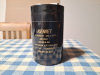
40Vdc caps are purrrfect
now - rails, again:
30Vdc : fun begins
35Vdc : fun permanent
35Vdc++ : even merrier
now - rails, again:
30Vdc : fun begins
35Vdc : fun permanent
35Vdc++ : even merrier
Very cool. I saw your note about using a 28 volt transformer. My experience has been your expected rail voltage will be roughly 1.3x the secondary voltage coming off the transformer with just a simple CRC. However, I'm happy with "even merrier" if it works out that way 🙂
yeah
multiplicator (ac to DC) is 1.41 for lightly loaded PSU filter
as you load it ( Class A) multiplicator decreases
it is practically in between 1.25 to 1.3 for our usual concoctions
example, with 18Vac sec, it is 24Vdc nominally, while more as 22V5 when actually measured
Thumb of Rule ....... rulezzzz
Hi Mightiness, what's the highest possible rail where the amp has a normal lifetime?40Vdc caps are purrrfect
now - rails, again:
30Vdc : fun begins
35Vdc : fun permanent
35Vdc++ : even merrier
few trivial changes ( some resistor values, zeners, some combing through cap voltages and re-checking bjt voltage/dissipation figures
say 45Vdc rails, Iq in range of 1A2 to 1A5
Drekload of Watts
but why - build bigger amp ........
say 45Vdc rails, Iq in range of 1A2 to 1A5
Drekload of Watts
but why - build bigger amp ........
Thanks, I was just curious, what 35Vdc++ meansfew trivial changes ( some resistor values, zeners, some combing through cap voltages and re-checking bjt voltage/dissipation figures
say 45Vdc rails, Iq in range of 1A2 to 1A5
Drekload of Watts
but why - build bigger amp ........

Seems you preferred a bit lower rails and higher Iq for the SIT version, yeah ZM?Conclusion !
My preferences:
-Babelfish XA252 (that being All Mos):
rails between 30 and 35Vdc - depending how much power is needed, Iq everything between 1A and 2A, depending how much aluminum is on disposal, BFR-22R
-Babelfish XA252 SIT:
rails 30Vdc, Iq 2A, BFR-22R
Hasta La Vista, Baby........ I'll be back!
I got bored waiting for this and have started making my own. I could only find the smd 3092 and used those.

I reckon it’s 50 50 if I get magic smoke! I should have waited for the real ZM one, especially as I still haven’t finished my Aleph J’s case.
I reckon it’s 50 50 if I get magic smoke! I should have waited for the real ZM one, especially as I still haven’t finished my Aleph J’s case.
I have gathered my (majority of) parts for xa252 (no SIT, no Schade) and SissySIT P. Thanks ZM, looking forward to receiving PCBs. I always second guess my own choices of parts so conveniently asked ZM to send full packages. At least then I remove that small factor of doubt from my mind. Look at the size of those supreme Toroidy transformers. The one in the back is from Toroidy as well and has equal specs😱. They are heavy and huge!
I did that with 6-24db crossover boards, still anxious to order. Also I need to find an efficient way or tool to match j113 fets. I must confess that I have the full xa252 schematic in easyeda as well, more for learning purposes😉I got bored waiting for this and have started making my own. I could only find the smd 3092 and used those. View attachment 1118549
I reckon it’s 50 50 if I get magic smoke! I should have waited for the real ZM one, especially as I still haven’t finished my Aleph J’s case.
What about this:
Pulled from the DIYaudiostore site.
- Get a 5 to 13 volt supply and a DC voltmeter (we used 12V)
- Connect the +V to the Drain
- Connect the Gate and Source together to a 100Ω resistor
- Connect the other lead of the resistor to ground
- Measure the voltage across the resistor, which gives the Idss (1 volt = 10 mA of current)
- Try to measure all devices under the same conditions, temperature, and duration of test.
Pulled from the DIYaudiostore site.
This has not stopped you and Pa feeding us greedy boys with this plenty power Class A though, luckily 🙂 but indeed, as Speels I also wonder, why THF51 on 30vdc only?I don't need much power for any of my spks
I've recently acquired an SMPS from MicroAudio. Oozes quality. Rails are around +/-33VDC and can deliver 15A peak.
Greedy boyz be greedy. > : )
I have also had the chassis and power supply, for this amp, for a year now 😱... Waiting waiting waiting...🙂
- Home
- Amplifiers
- Pass Labs
- Babelfish XA252 / Babelfish XA252 SIT / Babelfish XA252 SET