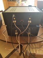

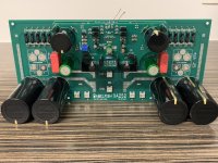
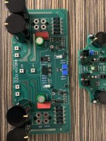
2nd and final iteration of output stage, front end and active rectifier PCB are finished.
As you can see on the OPS PCB, I added a few very nice to have features (at least for me). A clip indicator and a High/Low bias switch. Both will be connected to a power management and control PCB.
Low bias is adjustable between 1 and 1.5A, High up to 2.2A
I tried to use good components (as Zen Mod already mentioned, this amp deserves best): Mundorf and Nichicon caps, Mills MRA5 0R56 resitors. I've changed quite some transistors on the front end, in order to deal better with the power dissipation and or have a bit more Vds reserve.
For the front end, a cap multiplier has been added. Which drops the rails 0.7V.
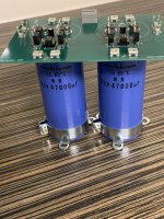
Total capacitance per rail is almost 100.000µF, which results in a ripple of about 30mV for the OPS.
Next is 2 thick aluminium heat spreaders (15x350x150mm) to bolt to 2x 2x 5u 210mm heigh Modushop heatsinks.
And some Toroidy 400VA supreme toroidals
As you can see on the OPS PCB, I added a few very nice to have features (at least for me). A clip indicator and a High/Low bias switch. Both will be connected to a power management and control PCB.
Low bias is adjustable between 1 and 1.5A, High up to 2.2A
I tried to use good components (as Zen Mod already mentioned, this amp deserves best): Mundorf and Nichicon caps, Mills MRA5 0R56 resitors. I've changed quite some transistors on the front end, in order to deal better with the power dissipation and or have a bit more Vds reserve.
For the front end, a cap multiplier has been added. Which drops the rails 0.7V.
Total capacitance per rail is almost 100.000µF, which results in a ripple of about 30mV for the OPS.
Next is 2 thick aluminium heat spreaders (15x350x150mm) to bolt to 2x 2x 5u 210mm heigh Modushop heatsinks.
And some Toroidy 400VA supreme toroidals
Attachments

Getting ready to test XA252 set with irfp mosfets before buying IXYS bucks and higher voltage transformer.
Would this heatsink 15x5x5 cm ok for quick test? What would be a good Iq mA for that when rail voltages are -+24V?

GBR resistor is 10 Ohm. R29 and R50 are jumpers. C12 and C13 are 820uF. Big three 5w resistors are 0,36 Ohms. Zeners are 0,5 w - is this wattage rating ok?

Would this heatsink 15x5x5 cm ok for quick test? What would be a good Iq mA for that when rail voltages are -+24V?
GBR resistor is 10 Ohm. R29 and R50 are jumpers. C12 and C13 are 820uF. Big three 5w resistors are 0,36 Ohms. Zeners are 0,5 w - is this wattage rating ok?
I need some help before I go on. It blows negative side fuse sometimes switching on and off. I have quite large 40 mF cap bank for each side (total 8x 10mF) no resistors between these caps and fuse before that cap bank  . That inrush for the caps affects this 4A fuse a lot even with having a Chinese soft-start. Testing this with rail voltage 24 V. M2 and Q9 heatsinks are getting quite hot. Mosfets from Papas F5m even do not get warm during that time 30-60 seconds. LEDs are turning on. P2 Iq pot value about 400 ohm. DMM shows 0.0068 V between 0,14 ohm resistors. Offset 0V. Could be that I have blown something during testing when I lost negative side psu voltage and offset showed on that time 15 V or more? Something else went wrong? 😕I run out of fuses to test further.


. That inrush for the caps affects this 4A fuse a lot even with having a Chinese soft-start. Testing this with rail voltage 24 V. M2 and Q9 heatsinks are getting quite hot. Mosfets from Papas F5m even do not get warm during that time 30-60 seconds. LEDs are turning on. P2 Iq pot value about 400 ohm. DMM shows 0.0068 V between 0,14 ohm resistors. Offset 0V. Could be that I have blown something during testing when I lost negative side psu voltage and offset showed on that time 15 V or more? Something else went wrong? 😕I run out of fuses to test further. Zenmod, any movement on new board?
Russellc
working on it, both physically on populating new gen of boards and also mentally what's best scenario for mild changes on existing ones
I need some help before I go on
when I did mention - several times, for several of my amps - to include temporary fuses in rails, I was always writing of including them in between PSU and amp itself
what means - fuses are after PSU caps, so no inrush surge affecting them
arrange that in that way and proceed
Q1/Q2 heatsink - with 24V rails there is apporx. 800mW of heat' expect 45C or so; with full rails there is slightly less than 1W2, so 55-60C is normal
same numbers applies to Q9, both for 24 and full rails
ignore ohmic reading for P2; turn it all CCW prior to powering up, put one Vmeter across rail resistor group, second Vmeter at output, so observe Iq and output offset
power it up and - if all survived previous tortures, you'll be able to get both Iq and offset in ballpark
last time I was at Sea Ranch, he made me sign an agreement - he's going to make all simple ones, so that is leaving only unnecessary complicated ones to me
which is, more than once, explained - Babelfish is title of amp branch, and "unnecessary complicated iteration of Papa's" is shortest description
though, in most cases, there is same number of active stages in my Babelfishes as in original ones
heck, I even learned his stage numbering technique, so few of them I described as no-active-stages amps

anyhow, I'm learning ..... I've just made 4 different preamps ......... and I realized yesterday - none of them having even one sole trimpot inside
go figure

edit: I remembered also - I have both Babelfish F5 and Babelfish F6, with just one trimpot per channel
which is, more than once, explained - Babelfish is title of amp branch, and "unnecessary complicated iteration of Papa's" is shortest description
though, in most cases, there is same number of active stages in my Babelfishes as in original ones
heck, I even learned his stage numbering technique, so few of them I described as no-active-stages amps
anyhow, I'm learning ..... I've just made 4 different preamps ......... and I realized yesterday - none of them having even one sole trimpot inside
go figure
edit: I remembered also - I have both Babelfish F5 and Babelfish F6, with just one trimpot per channel
Sorry, I meant before. My fuse is before active synchronous rectification diode. I will make some temporary fix for that. First time when I turned the Iq up tp 400 ohm resistance DMM did not show any movement. I will try later on when I have proper set up for this. During that time Q1 and Q2 where not hot or warm to feel them like Q9 (TTC004b) and M1 (DN2540).what means - fuses are after PSU caps, so no inrush surge affecting them
I tried today again with 2,5A fuses after PSU. One time it blowed positive rail fuse when P2 was about 415 ohm. Then I changed the fuse and turned P2 all the way to max resistance 500 ohm. Then it blowed the negative rail fuse. This time no green leds on but only very short flash from them. How to proceed next? 🥹
I have uploaded a short 18 seconds video to google drive. Click here.
I have uploaded a short 18 seconds video to google drive. Click here.
if you go back, you'll find explained procedure with schematic how to test circuit without output mosfets connected, thus preventing BigBadaBoom scenario
regular drill is - checking all parts for proper position and value, testing all semis with diode test in situ, then pulling those suspicious, checking them out of circuit
problem you made with irregularly placed fuses is that you invoked situation with one rail missing, while still having enormous stored energy in cap banks, so it is absolutely impossible to construct any scenario what could go wrong .... practically - everything is suspicious
now, what I learned in dozen decades of service work - Blind Hen approach is in some cases*** , paradoxically, fastest - pull put one by one all active parts and check them out opf circuit, put back what's OK< replace what isn't
*** not having enough mileage and knowledge to check in situ, or having both but complexity of circuit and lack of schematic making it same .........
I have some questions. 🙂 I started to populate next pcb. I do not have such a skills yet to find parts that needs to be replaced. Specially when parts are still in pcb. My plan was to fully populate next pcb and then I can compare these DVM values and unpopulate parts to make final testing for ok.
I received my ordered C6 47uF cap kind a smashed a little bit and I do want risk populating it to that place. Right now I have by hand 18uF, 100uF and 120uF caps. Whould some of these be ok for replacement?
I received my ordered C6 47uF cap kind a smashed a little bit and I do want risk populating it to that place. Right now I have by hand 18uF, 100uF and 120uF caps. Whould some of these be ok for replacement?
Do I need to connect some wires after taking them off?remove M2 and Q9 for that
All the suspicious parts measure with the diode test the same with the new untested populated board. 🙄 Do I leave n.f resistor and a n.f cap unpopulated?
Last edited:
C6 can be anything between 22uF and 220uF
two temporary wires are shown in sch you linked in #2416
you need all parts, except big pucks, for test shown in linked post, if your question is in that context
of course, with omission of level shifting parts, M2 and Q9
Do I need to connect some wires after taking them off?
two temporary wires are shown in sch you linked in #2416
Do I leave n.f resistor and a n.f cap unpopulated?
you need all parts, except big pucks, for test shown in linked post, if your question is in that context
of course, with omission of level shifting parts, M2 and Q9
- Home
- Amplifiers
- Pass Labs
- Babelfish XA252 / Babelfish XA252 SIT / Babelfish XA252 SET