for initial setting procedure - inputs shorted, no load at outputs
you can't expect normal output offset as long you don't get it at least 50% biased for Iq
patience is needed, initial filling of capacitance between output gates ........
start with one channel only, and when you have first set, solder rails to second one and proceed
you can't expect normal output offset as long you don't get it at least 50% biased for Iq
patience is needed, initial filling of capacitance between output gates ........
start with one channel only, and when you have first set, solder rails to second one and proceed
Hi @Plott - That is the Antek AS-3218. With primaries all shorted together and one side of the secondary shorted, and after multiple tries over 2 days, the Snubber value I am using as depicted on my O-scope is C3 (Cs) = 0.15uF C2 (Cx) = 0.01uF Rs=47. The curve looked okay using values anywhere from 35R to about 52R. I chose 47R 1/2w because it’s what I had in my stash.Good to see your progress @glenv6 , thanks for sharing!
Is the donut an Antek 3218? If so, what is your Quasimodo snubber value?
I will caution you though, the values reported on the Quasimodo Results (Only) thread for this traffo are very different at 10R to 12R. One poster reported anything less than 22R. I could not reproduce those results in any configuration of shorted or series wiring on my AS-3218. I have not tested my Quasimodo to see if something is off, though I do get results similar to others testing a different traffo.

CLC SissySIT is a recipe for big smiles. Nice work!Thought I would share the progress I am making on my SissySIT R.3 . After assembling the boards, Quasimodo led the way on the R value for the Snubbers. Scratching a particular diy itch, I decided to go with a Hammond 159ZJ based CLC PSU with 33,000uF Cornell Dubilier 380LX caps. These caps have a 6.84 amp Ripple Current, which along with the Hammonds, ought to keep things smooth, quiet and under control.
Next up, I am playing around with component placement in the Modushop monoblocks. Then wiring. Then component testing before finally lighting these puppies up to crank out some sweet sounds.
View attachment 1099845View attachment 1099846
for initial setting procedure - inputs shorted, no load at outputs
you can't expect normal output offset as long you don't get it at least 50% biased for Iq
patience is needed, initial filling of capacitance between output gates ........
start with one channel only, and when you have first set, solder rails to second one and proceed
Yes, using shorted input, no load and only one side at a time with single fuse.
@rhthatcher - Thanks! Your CLC Sissy was one of many that provided the inspiration. I went back and forth between contemplating a Cap Mx and a CLC for this build. The CLC won out for many good reasons, one being I can always revert to CRC if things go sideways.
BTW, those little boards you sold me for the CL-60 “soft start” and Bridge/Snubber are tremendous time and space savers - Thank you!
This diyaudio community is the best!
BTW, those little boards you sold me for the CL-60 “soft start” and Bridge/Snubber are tremendous time and space savers - Thank you!
This diyaudio community is the best!
Yes, using shorted input, no load and only one side at a time with single fuse.
thermal goop between bridges and base plate?
and split washer for bridge screw is a must, or self-locking nut, as Pa use in FW
air-fixed mains NTCs are sorta scary ........

Thermal goop between bridges and base plate: will add it.
Split washer for bridge screw is a must: are on other side.
Air-fixed mains NTCs are sorta scary : temporary situation, will fix to something.
"power it up , observe output - no more than 1V or so allowed ..... if more , something is fishy - power it off and cry here": 😢 3V one side and other 6V, will check all pot settings first. P1 is at 0R.
"In same time - DVM across 0R1 must stay pretty much undecided ..... few mV or so are allowed": 0 mV
In hindsight, the UMC spec would have worked, but I made this in visio
template link
The edge of the paper was supposed to line up with the end of the board, but its a little off.
template link
The edge of the paper was supposed to line up with the end of the board, but its a little off.
Desperately need new multimeters 😡, one is broken now so this is not ideal. Have got right channel Iq up to 180mV getting nice and warm, offset is not going lower than about 1V though.
left channel can get same Iq reading but not getting so warm at all and having offset of 6V not changing. Giving up for now, will first order new fresh/better meters than current old crap.
left channel can get same Iq reading but not getting so warm at all and having offset of 6V not changing. Giving up for now, will first order new fresh/better meters than current old crap.
Uni-T 133a ok? I see you use Uni-T.
BAF with new PapaSIT😍
 arrives tomorrow at least this is what I think. Time to get more Tokins.
BAF with new PapaSIT😍
arrives tomorrow at least this is what I think. Time to get more Tokins.Uni-T are in general good drek
I wish I had that quality for that money few decades ago ...... at least I would feel cleverer

I wish I had that quality for that money few decades ago ...... at least I would feel cleverer
Same again. Right channel Iq right quite steady180mV and nice warm heatsink both IRFP and THFHave got right channel Iq up to 180mV getting nice and warm, offset is not going lower than about 1V though.
left channel can get same Iq reading but not getting so warm at all and having offset of 6V not changing. Giving up for now, will first order new fresh/better meters than current old crap.
offset not lower than 850mV at end of offset adjustment - click.
Last edited:

Sorry for the editing, whole night of measuring, checking, etc. So actually still not doing what it should.
How is offset supposed to work; it seems now it is a positive offset, turning pot gives either more positive offset or lowest possible is still positive offset about 850mV in my right channel which is behaving the most normal. Something is just not right, and don’t get me started on the left channel which is drawing current with Iq-pot completely at 0R and 6V offset. But THF and mosfet in that channel are not even getting warm even with Iq on reasonable level.
How is offset supposed to work; it seems now it is a positive offset, turning pot gives either more positive offset or lowest possible is still positive offset about 850mV in my right channel which is behaving the most normal. Something is just not right, and don’t get me started on the left channel which is drawing current with Iq-pot completely at 0R and 6V offset. But THF and mosfet in that channel are not even getting warm even with Iq on reasonable level.
few questions:
- do you know Ugs of SITs you have , for values as it was usual way of testing - 24Vdc and 2A?
- did you triple check orientation and positioning of all parts on pcb?
-DC offset on working channel is positive or negative? you can be sure of that measurement simply knowing that black DVM probe is connected to GND (black speaker post) and red to positive speaker post
- what exactly values you have put for R18, R19 and P2?
-what is current in left channel, which is drawn in start?
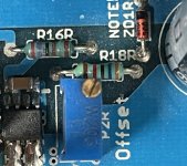
-orientation of ZD1 on left channel
all referenced to schm in post #1
- do you know Ugs of SITs you have , for values as it was usual way of testing - 24Vdc and 2A?
- did you triple check orientation and positioning of all parts on pcb?
-DC offset on working channel is positive or negative? you can be sure of that measurement simply knowing that black DVM probe is connected to GND (black speaker post) and red to positive speaker post
- what exactly values you have put for R18, R19 and P2?
-what is current in left channel, which is drawn in start?
-orientation of ZD1 on left channel
all referenced to schm in post #1
Ugs of SITs according to when I bought them from Pras: 3,25V and 3,26V at 24V 2A on label.few questions:
- do you know Ugs of SITs you have , for values as it was usual way of testing - 24Vdc and 2A?
- did you triple check orientation and positioning of all parts on pcb?
-DC offset on working channel is positive or negative? you can be sure of that measurement simply knowing that black DVM probe is connected to GND (black speaker post) and red to positive speaker post
- what exactly values you have put for R18, R19 and P2?
-what is current in left channel, which is drawn in start?
-orientation of ZD1 on left channel
all referenced to schm in post #1
It’s three years since I soldered everything, I will recheck all the parts. Did check the pots again yesterday those are ok.
Working channel offset is positive, can only adjust it in positive range, not reaching negative. I would expect a positive-negative adjustment range to reach the zero-crossing.
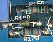
Ok just visually checked all the resistors and have 36k on R18 instead of 43k? and 3k on R19 instead of 36k which is also smaller resistor? Everything else seems to check out and same on both boards.
I do believe I took care of ZD1 orientation as inverted.
Attachments
- Home
- Amplifiers
- Pass Labs
- Babelfish M25, SissySIT - general building tips and tricks