have you some raw pcbs ?
cap bank pcb ......... all you need is some brain , few drills and exacto knife
metal ruler is helpfull too
and you'll have custom pcbs then
pcb from store is ok , but I really prefer option with two bridges per xformer
Lol, I’m still just a simpleton when it comes to this, but I do super well with pictures that show me what to do. You have any more angles of close ups by chance?
no pics , but I can make some sketches for you
Thanks, looking online at blank or raw pcb boards... what size should I look for? Any particular characteristics or specs it should have?
New builder here sort of, so I will need a bit of guidance... even brand recommendations would be great. I know from thread I want to do dual mono, and it seems like most are using 33,000uf 35v.. I see banks of either 4 or 8 on each side... and some of you have motorruns... what does that do? What do I you recommend?
with regular FW rails format , that would be around 22V5dc gotten from 18Vac secondaries, you can use 25Vdc caps ...... and Papa taught us that we can be cheapskates without consequences sometimes 
Panasonic, CDE , whatever well known brand ..... plenty of them at digikeee and mowser
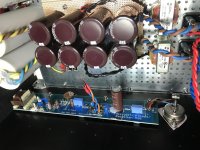
best dual mono , so 33mF-0R1-33mF per rail
50uF (and up) motor runs , bypass for last 33mF , as idea to speed up things .... or just sleep better , or show off more in front of your audio buddies (where you can add broader greenie while you're sleeping good)
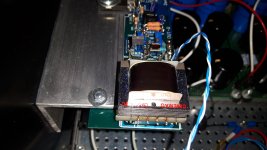
see pics of my recently made SissySIT , as example of cap bank pcbs ; caps are 35Vdcc jobbies , 35mm dia ..... so you can grasp dimensions easier
generally - when you have caps in your hands , that's time for pcb layout - not because you can't read dia and pins pitch from datasheet , but because only then you're sure that there is nothing to change in last moment
Panasonic, CDE , whatever well known brand ..... plenty of them at digikeee and mowser
best dual mono , so 33mF-0R1-33mF per rail
50uF (and up) motor runs , bypass for last 33mF , as idea to speed up things .... or just sleep better , or show off more in front of your audio buddies (where you can add broader greenie while you're sleeping good)
see pics of my recently made SissySIT , as example of cap bank pcbs ; caps are 35Vdcc jobbies , 35mm dia ..... so you can grasp dimensions easier
generally - when you have caps in your hands , that's time for pcb layout - not because you can't read dia and pins pitch from datasheet , but because only then you're sure that there is nothing to change in last moment
Some SissySIT experiences from my side:
As written here before, I tried to build the SissySIT with the combination of THF-51S and Toshiba 2SJ201. While they measured about 0.5V apart in Vgs when characterizing them at 2A and 24V, in-circuit the Vgs difference turned out not to be sufficient. They might have run a bit cooler when measuring Vgs – smaller heat sink, but fan-cooled.

I built one channel with THF-51S and 2SJ201. With the bias pot at zero, current at power-up immediately was 1 to 1.2 A. The bias current could be set quite well with the pot at 2.0 A. However, there was also some DC on the output at power-up and shutdown (up to about a Volt, dissipating within a few tens of seconds with an 8 Ohm load on the output). Also, bias was highly dependent on device temperature and rail voltage. And the output offset voltage was quite sensitive to variations in rail voltages. The amp was well-behaved on the scope with -3dB at about 33 kHz.
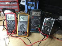
I then measured the Vgs difference in-circuit between the THF-51S and the 2SJ201. And this was actually less than 200 mV at power-up, and did not rise to more than 320 – 330 mV at stable operating conditions and heated up. Probably not enough for the optocoupler bias to work properly. Also, because the Vgs both were in the -2 to -2.5V range, the voltage drop over P2+R18 vs R19 at power-up is distributed in a way that even with the bias pot at zero and no charge in the bias capacitor, the gates were already partially open.

In the picture above, from left, you can see the Vgs of the 2SJ201, the THF-51S, the AC in voltage, and the bias current (I did use 0.05 Ohm resistors in the negative rails for measuring bias current). These measurements were taken with the heatsink fully warm.
In light of this, I abandoned the idea of using 2SJ201 and ordered a bunch of IRFP9140 (International Rectifier), and built both channels with IRFP9140. With these in the circuit, power-up behaviour was much more benign, but the susceptibility of bias current to temperature and rail voltage remained. Also the strong sensitivity of output offset to rail voltage variations. Oh well, but anyway, here goes … 😛

Mains voltage is not constant at my house, often fluctuating quite quickly, but mostly staying between 220V and 230V. In light of this, I have assessed the amp’s parameters at voltages between 220V and 230V, and set the operating points at 225V. I did control the voltage through a variable isolation transformer (amp was floating during this, with no earth connection).
I run the amp at 2.0 A and about 24V rails (at 225 V mains voltage). Once in thermal equilibrium, the bias stays stable. Bias rises with rising temperature, and also is quite susceptible to variations in rail voltage. A 2% variation in mains voltage translated to a 2% variation in rail voltage and about a 5% variation in bias current.
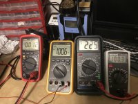
The output offset also is dependent on rail voltages. When I set it for zero at 225V mains (+/- 24V rails), it goes to about -40 mV at 230V mains (~24.5V rails) and maybe +60 mV at 220V mains (~23.5 V rails). However, setting output offset with the trimmers works well and smoothly, and offset stays stable (resp. returns to zero when the rails are returning to the same value where you had set it 😀).

The picture above shows, from left, output offset of one channel, bias current for the left channel, AC input voltage, bias current for the right channel (again, bias measuring resistors were 0.05 Ohm). Once fully warmed up and with AC input voltage held constant, nice and stable.
Some DC on the outputs during power-up and shutdown, quickly dissipating when loudspeaker resp 8 Ohm-load is connected.. No turn-off thump, and a very low one at turn-on.
Gain is a little less than 4x. Frequency response is -3 dB at 31-32 kHz on treble. In the bass, below 10 Hz the waveform doesn’t decrease much in amplitude, but gets increasingly distorted, probably because of the gain transformer. Square waves are clean, but the 10 kHz square wave obviously is already severely rounded off. A 10 Hz square wave shows asymmetric overshoot at the top and bottom halves.

The amp is totally quiet, nothing to hear with my ear at the drivers of my 100 db/W efficient speakers. Much quieter than my M2, where you could still hear a faint hum with the ear at the driver.
It also sounds already very good, even though it has only been in operation for a few hours. Very clean, much more detail / information than my M2. In the first few hours, sometimes a bit aggressive on modern pop recordings (d’uh ! what a surprise … 🙄) Very smooth and beautiful string tone, when the recording has it. Every CD sounds different, which in my book is a very positive thing for an amplifier to show. Will try LPs soon.
Best regards,
Claas 🙂
As written here before, I tried to build the SissySIT with the combination of THF-51S and Toshiba 2SJ201. While they measured about 0.5V apart in Vgs when characterizing them at 2A and 24V, in-circuit the Vgs difference turned out not to be sufficient. They might have run a bit cooler when measuring Vgs – smaller heat sink, but fan-cooled.
I built one channel with THF-51S and 2SJ201. With the bias pot at zero, current at power-up immediately was 1 to 1.2 A. The bias current could be set quite well with the pot at 2.0 A. However, there was also some DC on the output at power-up and shutdown (up to about a Volt, dissipating within a few tens of seconds with an 8 Ohm load on the output). Also, bias was highly dependent on device temperature and rail voltage. And the output offset voltage was quite sensitive to variations in rail voltages. The amp was well-behaved on the scope with -3dB at about 33 kHz.
I then measured the Vgs difference in-circuit between the THF-51S and the 2SJ201. And this was actually less than 200 mV at power-up, and did not rise to more than 320 – 330 mV at stable operating conditions and heated up. Probably not enough for the optocoupler bias to work properly. Also, because the Vgs both were in the -2 to -2.5V range, the voltage drop over P2+R18 vs R19 at power-up is distributed in a way that even with the bias pot at zero and no charge in the bias capacitor, the gates were already partially open.
In the picture above, from left, you can see the Vgs of the 2SJ201, the THF-51S, the AC in voltage, and the bias current (I did use 0.05 Ohm resistors in the negative rails for measuring bias current). These measurements were taken with the heatsink fully warm.
In light of this, I abandoned the idea of using 2SJ201 and ordered a bunch of IRFP9140 (International Rectifier), and built both channels with IRFP9140. With these in the circuit, power-up behaviour was much more benign, but the susceptibility of bias current to temperature and rail voltage remained. Also the strong sensitivity of output offset to rail voltage variations. Oh well, but anyway, here goes … 😛
Mains voltage is not constant at my house, often fluctuating quite quickly, but mostly staying between 220V and 230V. In light of this, I have assessed the amp’s parameters at voltages between 220V and 230V, and set the operating points at 225V. I did control the voltage through a variable isolation transformer (amp was floating during this, with no earth connection).
I run the amp at 2.0 A and about 24V rails (at 225 V mains voltage). Once in thermal equilibrium, the bias stays stable. Bias rises with rising temperature, and also is quite susceptible to variations in rail voltage. A 2% variation in mains voltage translated to a 2% variation in rail voltage and about a 5% variation in bias current.
The output offset also is dependent on rail voltages. When I set it for zero at 225V mains (+/- 24V rails), it goes to about -40 mV at 230V mains (~24.5V rails) and maybe +60 mV at 220V mains (~23.5 V rails). However, setting output offset with the trimmers works well and smoothly, and offset stays stable (resp. returns to zero when the rails are returning to the same value where you had set it 😀).
The picture above shows, from left, output offset of one channel, bias current for the left channel, AC input voltage, bias current for the right channel (again, bias measuring resistors were 0.05 Ohm). Once fully warmed up and with AC input voltage held constant, nice and stable.
Some DC on the outputs during power-up and shutdown, quickly dissipating when loudspeaker resp 8 Ohm-load is connected.. No turn-off thump, and a very low one at turn-on.
Gain is a little less than 4x. Frequency response is -3 dB at 31-32 kHz on treble. In the bass, below 10 Hz the waveform doesn’t decrease much in amplitude, but gets increasingly distorted, probably because of the gain transformer. Square waves are clean, but the 10 kHz square wave obviously is already severely rounded off. A 10 Hz square wave shows asymmetric overshoot at the top and bottom halves.
The amp is totally quiet, nothing to hear with my ear at the drivers of my 100 db/W efficient speakers. Much quieter than my M2, where you could still hear a faint hum with the ear at the driver.
It also sounds already very good, even though it has only been in operation for a few hours. Very clean, much more detail / information than my M2. In the first few hours, sometimes a bit aggressive on modern pop recordings (d’uh ! what a surprise … 🙄) Very smooth and beautiful string tone, when the recording has it. Every CD sounds different, which in my book is a very positive thing for an amplifier to show. Will try LPs soon.
Best regards,
Claas 🙂
Attachments

Wow, that’s great news and some nice photos. I’m still waiting for the dodo to drop off my boards.
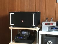
What preamp is in your last photo?
What preamp is in your last photo?
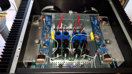
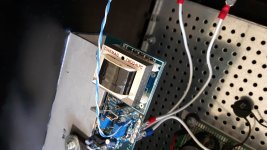
The preamp is an Aikido. I put the amp boards into a case that I bought from China, complete with a relay-based stepped volume control.(Was offered as "passive preamp")
I threw out the mains transformer so I had space for the Aikido boards, and added a totally overkill separate PSU, connected by an umbilical carrying all regulated B+, heater voltage, and control voltage. Had some nice parts leftover from a prior upgrading session of my 2A3 poweramp. 😀
I can re-configure the Aikido as an ACF (Aikido cathode follower) by changing two resistors on the board (have them socketed for easy changes), and replacing the gain tubes with a capacitor. That works well for higher gain amps. In the picture, it was still configured that way. Have changed it back to a regular Aikido now because of the low gain of the SissySIT.
I am running 5687s as the gain tubes at the moment, and 6N6P as the followers. Have also had very nice sound with E80CC as gain tubes.
Best regards, Claas
Last edited:
SissySIT and Cinemags CMOQ-4LPC
Today I had my first meeting with the Cinemag transformers. The replacement of the Edcor that were mounted was easy including the removal of R13 and C3. I omit the boring fact of having to dismantle the Heatsink to be able to work on it. Previously I had replaced the gate resistances of 9140 and SK180 (respectively 100R and 200R) with Vishay Z-foil Charcroft .... I strongly recommend this intervention because the signal passes through these resistances and critical listening places them as irreplaceable .... I'm not telling you stories ... if you can mount them and you won't regret. Let's talk about Cinemag: you don't have to think ... you don't have doubts ... they are magic. You will forget on the spot that the Edcor have existed in the Sissy. There is no aspect that is not improved. There is superior resolution, every detail is presented with clarity and expressiveness, but with sweetness without haste. The timbre of each instrument is perfect easily distinguishable. I was particularly struck by the clear difference in the low, powerful, articulated and deep sounds (a lot of difference with the Edcor where there was more confusion and some difficulty to unravel the timbres). The stage presentation is different with Cinemag. The scene widens and its depth, however everything is perfectly focused, nothing is in the shade. Wonderful voices (from emotion).
This creature from Zen Mod under the protective wing of the Great Nelson ... The SissySIT ... I call it a happy amp ... a masterpiece. Guys make a sacrifice and assemble the Cinemags ... they are what we need as a necessary ingredient.
Attachments

re: stability of bias and offset
Oh, by the way, setting bias and offset for the front-end buffer was absolutely straightforward and easy. And it stayed absolutely stable and rock-solid at 20 mA bias and 0.0 mV offset even under variations of rail voltages ... 🙂
One small maybe interesting side-fact: I initially set the buffer when the amp was still connected to the variable isolation transformer, so that I had control over AC input voltage / rail voltages. In this configuration, the amp had no earth connection and was floating.
When I re-checked the buffer settings with the amp connected directly to mains, and therefore a ground / earth connection, I found that the bias had dropped to about 18.5 mA. Once re-set, it was absolutely stable again.
Best regards,
Claas
That’s a very nice review, papa once said that the cinimags measure only slightly better than the Jensen’s. So don’t Limit yourself to one spun copper device.
Also a duller device might be better on a compression driver.
What speakers are you shaking home with?
Also a duller device might be better on a compression driver.
What speakers are you shaking home with?
'Talian ones , as already written several posts back
don't mess with 'Talians , when speakers , motorbikes and vino are in question
oh yes - I'm driving 'Talian car ,also having Guzzi in garage , to enjoy as soon I find time , to make it even more 'Talian than it is now
don't mess with 'Talians , when speakers , motorbikes and vino are in question
oh yes - I'm driving 'Talian car ,also having Guzzi in garage , to enjoy as soon I find time , to make it even more 'Talian than it is now

- Home
- Amplifiers
- Pass Labs
- Babelfish M25, SissySIT - general building tips and tricks