DC offset at output of JFet buffer (at jumper, open) and Iq of same set as 20mV across 1R resistor?
no Borbely WCF thingies , straight one?
cascode transistors in proper places , etc?
no Borbely WCF thingies , straight one?
cascode transistors in proper places , etc?
Hmm Cal....
you got me thinking the other day - looking at post #807
I actually haven't used those speakers again and know that the default to many who use this amp are full range speakers but wonder if you and I were seeing a similar behaviour. The amp sounds great with conventional speakers that use a crossover / zobel network.
..dB
you got me thinking the other day - looking at post #807
Curious if anyone has run 12ohm full range with sissy. I was testing out my Moth Cicadas last night and it seemed sissy was oscillating?
I didn't get sound, only odd scratching noise and a "pft pft" before I shut it down. I pulled speaker cables and fired it up and measure dc offset, normal, plugged in different speakers and normal sound. Plugged the Moths into a different amp, normal music. Tried sissy again and same odd behavior?
.. dB
I actually haven't used those speakers again and know that the default to many who use this amp are full range speakers but wonder if you and I were seeing a similar behaviour. The amp sounds great with conventional speakers that use a crossover / zobel network.
..dB
DC offset at output of JFet buffer (at jumper, open) and Iq of same set as 20mV across 1R resistor?
no Borbely WCF thingies , straight one?
cascode transistors in proper places , etc?
Commuting to work, but will check tomorrow. No borbelys. Which are the cascode transistors?
Thanks.
my RCA LC1 are full range, 16R
15" having nothing as xover , centrally mounted tweet having just 4uF in line
no problems
15" having nothing as xover , centrally mounted tweet having just 4uF in line
no problems
Hmm Cal....
you got me thinking the other day - looking at post #807
I actually haven't used those speakers again and know that the default to many who use this amp are full range speakers but wonder if you and I were seeing a similar behaviour. The amp sounds great with conventional speakers that use a crossover / zobel network.
..dB
Thanks for the thought db. It's not speaker specific though, happens on both crappy and nice speakers for one channel, works on both for the other.
The reason I found out on the nice speakers was because I turned on the amp with my preamp off there, but my phone on (but without music playing) when testing.
Commuting to work, but will check tomorrow. No borbelys. Which are the cascode transistors?
Thanks.
BD139 and BD140 ; due to them , you have around +/-10V for buffer
Also, in case it helps, the motor boating sound starts in the low frequencies and rapidly moves up to tweeter range over the course of a second or two. It might stop after that, but I haven't had the courage to do anything besides cut the power once it starts.
just check proper setting and rails of input JFet buffer ; also possible test - trying the same ( as when motorboating happen previously) with small jumper removed , so no signal route from JFet buffer to xformer and OS
that can locate where culprit is - in buffer or afterwards
that can locate where culprit is - in buffer or afterwards
1. Cascode transistors in correct locations.
2. 3.45v from pin 4 of octocoupler to ground.
3. 4.4v from pin 3 of octocoupler to ground.
4. No motorboating if jumper is removed.
2. 3.45v from pin 4 of octocoupler to ground.
3. 4.4v from pin 3 of octocoupler to ground.
4. No motorboating if jumper is removed.
voltage across R8 (1R) ? it should be in range of 20mV
voltage at buffer output , jumper removed - you can see which pin of jumper header is on buffer's side - it should be minimal , ideally 0mV ref. to GND
also measure DC voltages at R8 (any pin) and RB (any pin) ref to GND
voltage at buffer output , jumper removed - you can see which pin of jumper header is on buffer's side - it should be minimal , ideally 0mV ref. to GND
also measure DC voltages at R8 (any pin) and RB (any pin) ref to GND
DC offset at output of JFet buffer (at jumper, open) and Iq of same set as 20mV across 1R resistor?
no Borbely WCF thingies , straight one?
cascode transistors in proper places , etc?
5. 5mV between jumper pin 1 and ground.
6. 19.9mV across R8.
voltage across R8 (1R) ? it should be in range of 20mV
voltage at buffer output , jumper removed - you can see which pin of jumper header is on buffer's side - it should be minimal , ideally 0mV ref. to GND
also measure DC voltages at R8 (any pin) and RB (any pin) ref to GND
7. 10.02V R8 to ground.
8. 11.10V RB to ground.
Both measured with jumper removed.
Last edited:
everything looking good ....... you can try to decrease 5mV to zero, with R7 trimpot ; be sure that you're measuring on proper pin ( one is buffer side , second is xformer side)
reconnect jumper and try again
if you still have motorboating , disconnect jumper and try feeding an amp post buffer - connecting some decent source (DC free please!) to amp's GND and jumper header pin at xformer side
if you tell me which channel is in case ( what's written on pcb) I can pinpoint you which pin is which , with small pic
Adjusted R7 to get down to 0.1mV, reconnected buffer. Still motorboating when input short is removed.
It's the left channel...
It's the left channel...
And thanks again for all the help troubleshooting. At least I'm learning a tiny bit about how the circuit works...
so , as I understood you ( you probably didn't oriented probes properly ) , there is -3V45 at SIT gate (opto pin 4 ) and -4V4 at mosfet gate (opto pin 3 ) , both ref to GND , which means you have hefty 0V95 as voltage window for opto bjt
care to take some pics of let channel pcb , so we can take a peek at ?
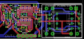
find enclosed little pic of relevant pins of jumper header ;
as shown on pic , upper pin is buffer's side , while lower pin is xformer's ( and rest of amplifier , downstream) side
try test with signal to lower pin ( do not forget gnd) , thus leaving buffer from story
though , logic dictates that you made some systematic mistake , same thing happening on previous left pcb and now on second ......
care to take some pics of let channel pcb , so we can take a peek at ?
find enclosed little pic of relevant pins of jumper header ;
as shown on pic , upper pin is buffer's side , while lower pin is xformer's ( and rest of amplifier , downstream) side
try test with signal to lower pin ( do not forget gnd) , thus leaving buffer from story
though , logic dictates that you made some systematic mistake , same thing happening on previous left pcb and now on second ......
Attachments
so , as I understood you ( you probably didn't oriented probes properly ) , there is -3V45 at SIT gate (opto pin 4 ) and -4V4 at mosfet gate (opto pin 3 ) , both ref to GND , which means you have hefty 0V95 as voltage window for opto bjt
care to take some pics of let channel pcb , so we can take a peek at ?
find enclosed little pic of relevant pins of jumper header ;
as shown on pic , upper pin is buffer's side , while lower pin is xformer's ( and rest of amplifier , downstream) side
try test with signal to lower pin ( do not forget gnd) , thus leaving buffer from story
though , logic dictates that you made some systematic mistake , same thing happening on previous left pcb and now on second ......
Yes, sorry, I didn't pay attention to +/- on voltage readings.
Source connected to pin 8 of transformer & ground (w jumper removed) = music. No motorboating if source is disconnected.
Pictures coming.
Also, I never got to this point with the "old" left channel board. The capacitor got melted before I got to test for sound...
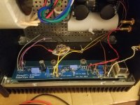
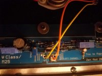
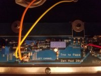
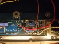
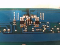
Pics...
Not my prettiest work and I did accidentally get the soldering iron on one of those boxed caps while attaching the SIT.
Not my prettiest work and I did accidentally get the soldering iron on one of those boxed caps while attaching the SIT.
Attachments

- Home
- Amplifiers
- Pass Labs
- Babelfish M25, SissySIT - general building tips and tricks