general rule, well, at least ZM's
up to 15W of heat per TO247 - you can use squishy silycone pads or cardbard, I don't care, it'll last
from 15 to 35W, use mica + goop
up from 35W to 50W, use either Keratherm 86/82 or Alumina pad + goop
proper torque, quality screws (stainless, if you can't find regular with data), split washer + 15mm Dia washer
proper torque means 0.9Nm
most critical for Keratherm, in fact, to avoid unequal squish
edit: above 50W - mount part directly to hsink, with some quality thermal goop, isolate heatsink from case; buy pack of handkerchieves - you'll need them sooner or later
Last edited:

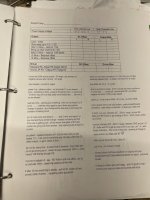
My notes in a binder with schematics and startup checksheets shows 1A8 was the set point in December 2019. One channel drifted high. Other channel drifted down a little.
How high? Who knows. It’s hard to say what the value was when it popped.
It’s been cooking about 7 hours today and I’m dialing both channels to 1A8 again.
How high? Who knows. It’s hard to say what the value was when it popped.
It’s been cooking about 7 hours today and I’m dialing both channels to 1A8 again.
Attachments
Last edited:
Good to know, thanks. I've got a SissySit that starts it's day at close to 2A, and goes up from there. I don't want to burn any FETs. 😳
He would make a joke saying the only way it is leaving his house is if a more powerful version could replace it!
for now, single candidate, of things I made, is Babelfish XA252 SIT
I still need to assemble my own demo specimen of B. XA252; sometimes being in trilemma which option, but then I'm thinking that clean mos is most killer one, if Audiophool target group

a SissySit that starts it's day at close to 2A
which iteration exactly?
initial or R.2?
That's actually a good idea, the binder🙂My notes in a binder with schematics and startup checksheets shows 1A8 was the set point in December 2019. One channel drifted high. Other channel drifted down a little.
How high? Who knows. It’s hard to say what the value was when it popped.
It’s been cooking about 7 hours today and I’m dialing both channels to 1A8 again.
Pass DIY Addict
Joined 2000
Paid Member
Indeed - a binder is an EXCELLENT idea! (he says after completing 31 channels of DIY goodness...) I have LOTS of electronic notes, just not all in one neat place that is accessible by others.
My SissySIT uses the original PCBs, and bias was set close to 1A8 shortly after power up, but this would creep up over several hours. I finally dialed it back down to 1A8 after leaving it run all day. This keeps wattage burn of the output devices to about 43-44w each. I've put aluminum ceramic insulator under the IRFP device, and I'd be more comfortable with one under the SIT as well. So far, it's been running about 16 hrs/day for more than a month without anything bizarre happening.
My SissySIT uses the original PCBs, and bias was set close to 1A8 shortly after power up, but this would creep up over several hours. I finally dialed it back down to 1A8 after leaving it run all day. This keeps wattage burn of the output devices to about 43-44w each. I've put aluminum ceramic insulator under the IRFP device, and I'd be more comfortable with one under the SIT as well. So far, it's been running about 16 hrs/day for more than a month without anything bizarre happening.
Pass DIY Addict
Joined 2000
Paid Member
Ha- After I got it dialed in, I just added it to the rack for the family room system. It gets turned on for the morning news at 7a, stays on most of the day when my wife is home, and gets turned off at 11p when it's time for bed. From time to time, I rotate amps through the system. In the winter, I tend to use the Aleph-J because it bakes off 200w of heat, helping to warm the house a little. During the summer, I tend to use a smaller amp with less heat output...
Pass DIY Addict
Joined 2000
Paid Member
Indeed she does! I was never more proud than the first time we went to an event with a DJ some time after I built my first amp (the a40). After a short while at the event, she turned to me and remarked, "WOW! That music sounds TERRIBLE, like it's all distorted or something."
I'm calling my Babelfish M25 with THF-51S a SissySit as the schematics are nearly identical save for the CCS module. Maybe that's not acceptable nomenclature.which iteration exactly?
initial or R.2?
After playing with the level shifters (a lot) I got the bias down where I wanted it, under 1.8A hot. Gosh does the offset wander around. Maybe it will be more stable with the lids on.
Left channel, ~194mV Iq (1.76A), offset +/- 30mV
Level shifter 166R4
THF-51S SIT gate -2V99
9140 gate -4V26
SIT drain 20V5
dissipation ~36W / device
Right channel, ~198mV Iq (1.8A), offset similar, +/- 30mV
Level shifter 180R
THF-51S SIT gate -3V
9140 gate -4V28
SIT drain 20V4
dissipation ~37W / device
I couldn't get these to match any better, what with the wandering values and the need for very specific level shifter values.
offset is noting to write home about and it'll be more stable when lid is closed - remember that regarding DC offset everything is passive - no any servo circ in sight ........ except maybe in some other gadget you have in room
so, figures you have are more than proper
now - Iq setting - everything is play with current through current mirrors, resulting in voltage sag across resistors in between mosfet gates (IRF510 up, IRFP9140 down) , then transposed 4V down+voltage sag across voltage level resistor, to reach SIT gate
now, when we were in correspondence and you had initial troubles (helped with my omission of sending 2pcs of BC546 for level shifting CCS and your omission to populate their position ), I was informedd that SITs you have are in much greater range of Ugs voltage ....... was it something as 5V5 figure?
now I see that they're -3V-ish ........ difference of 2somethingV resulting in somewhat less efficient correspondence
anyhow, fine tune of Iq possible through change of resistor in between mosfet gates, or change of level shifter resistor
so, figures you have are more than proper
now - Iq setting - everything is play with current through current mirrors, resulting in voltage sag across resistors in between mosfet gates (IRF510 up, IRFP9140 down) , then transposed 4V down+voltage sag across voltage level resistor, to reach SIT gate
now, when we were in correspondence and you had initial troubles (helped with my omission of sending 2pcs of BC546 for level shifting CCS and your omission to populate their position
), I was informedd that SITs you have are in much greater range of Ugs voltage ....... was it something as 5V5 figure?now I see that they're -3V-ish ........ difference of 2somethingV resulting in somewhat less efficient correspondence
anyhow, fine tune of Iq possible through change of resistor in between mosfet gates, or change of level shifter resistor
B-but Father, you've violated the Sanctity of the Confessional!! I was trying to be discreet, you know.
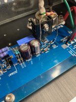
Yeah I ooked up, and ooked further with one channel before I figured out a part was missing. To include letting the gate of the SIT go open when under power. Regarding that, despite 8A coursing through half the circuit for a few seconds, no parts were obviously damaged... except this capacitor, which I noticed & replaced yesterday (please ignore the gate shifter aerial, lol).
Regarding Ugs. I guess I don't know what that means when it comes to a SIT. Vgs doesn't make sense to me with a depletion mode device because tying the gate to 0V means it's fully open. The values I gave were more properly Vth, as determined by hand with a frankentracer, and looking for a voltage drop across a source resistor. IOW the gate bias at which the SIT started conducting. Those values are as I said before, that is, -5V5 and -5V6. Is that inconsistent with the gate biases I reported for the channels when passing 1.8A?
Attachments
when passing 1.8A?
Ugs of SIT in working point of interest - which is 22-24V of Uds and Iq 1A8 to 2A
that's data useful for my peanut brain, to determine what /if /when some resistor need to be altered to enable proper settings
anyhow, you did it, even if our phones were semibroken
Hello!
I have four Tokin THF51 Ugs 3.4v(2A,24V).
Can I purchase a SissySit kit?
What does this require? Thank you.
I have four Tokin THF51 Ugs 3.4v(2A,24V).
Can I purchase a SissySit kit?
What does this require? Thank you.
- Home
- Amplifiers
- Pass Labs
- Babelfish M25, SissySIT - general building tips and tricks