well thats just it...even with a 1x gain there should be no distortion and I get this with either B1 or DCB1. In the past I had this same setup and had no distortion. I have not changed any parts on the BA3 so should be same as when I had it in my F4.
I stared long and hard at my BA3 and then realized...NO GROUND !!! lol maybe the next version of pcb they can have a dedicated star ground connection??
works great now 🙂 Just need to tweak the gain a little
works great now 🙂 Just need to tweak the gain a little
Awesome! Glad you figured it out!
There is no starground in order to facilitate doubling up everything to make a balanced stage, and also making it possible to cut the PCB in half if you wanted to mount it directly at the inputs.
There is no starground in order to facilitate doubling up everything to make a balanced stage, and also making it possible to cut the PCB in half if you wanted to mount it directly at the inputs.
In a related note...
I too noticed a lot of bias drift in my BA-3. Voltage stayed constant at 1V but DC offset drifted about 200mv from cold to warm. I tested it over an hour or so. Also, the pots were real twitchy. I slight movement really effected DC offset. I've yet to be able to get it under about 10mv...always jumps to far with adjustment.
I am using fairchild mosfets w/1K pots.
I have yet to hook mine up to an amp, still working out the volume and switch controls.
Hope this is normal, glad there is a cap on output.
In a related note...
I too noticed a lot of bias drift in my BA-3. Voltage stayed constant at 1V but DC offset drifted about 200mv from cold to warm. I tested it over an hour or so. Also, the pots were real twitchy. I slight movement really effected DC offset. I've yet to be able to get it under about 10mv...always jumps to far with adjustment.
I am using fairchild mosfets w/1K pots.
I have yet to hook mine up to an amp, still working out the volume and switch controls.
Hope this is normal, glad there is a cap on output.
I have Fairchilds and 1K pots like you and have the same behavior. I recently picked up some Toshibas and wondering if this might help. I have one channel stable but the other jumps all over the place. But I have used it like this and had no issues when coupled inside my F4.
Are both mofsets cool or hot or one hotter than the other? Is this where matched pairs would help?
Yes, one of my Mosfets is cooler than the other on each channel. They are unmatched. I don't know if it really effects bias stability though...
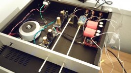
OK, my BA-3 has been up and running for a day. I'll save the "how it sounds" review for when I get a little more time to listen but so far so good. I have yet to fiddle with P3 but in the next couple of days I will. I can tell you it's very quiet and images well.
Lets talk about GAIN. I built the BA-3 with Nelsons stock values. Everyone said "too much gain, 30DB". But...
This preamp has less gain than my JFET BOZ (24DB). Way less. I'd say it's more around 10DB. I was pushing my F5 w/the BA-3 last night, it was loud, very loud but I almost maxxed out the volume control. I am running a 2MV HOMC cart into a 36DB phono stage (not much gain there) and using 91DB sensitive 8 ohm speakers.
I looked around on the main BA-3 thread and other people are reporting less than expected gain as well. I have no tools to take measurements but 30db is not happening for me.
Either that or it's built wrong. But my voltages are correct and everything sounds good. Actually, I am happy w/how much gain it has currently, I just was expecting more.
I too noticed a lot of bias drift in my BA-3. Voltage stayed constant at 1V but DC offset drifted about 200mv from cold to warm. I tested it over an hour or so. Also, the pots were real twitchy. I slight movement really effected DC offset. I've yet to be able to get it under about 10mv...always jumps to far with adjustment.
My statement might not apply to your issue, but because of symmetry, I like to use a power supply for each channel. Something always bothered me about using one power supply for two channels. I have used one PS for 2 channels, but rarely. Something about sharing the +/- voltage with 2 varying loads. Maybe that's that not the right way to word it.
I'm just thinking out loud here.

Attenuator /volume pot for BA-3 FE, and power supply questions
I'm planning on building one of these to go with an F4. Earlier in the thread it says a 20K attenuator is preferable. I already have a 50K Alps blue velvet on hand from another project that was never used. I don't mind ordering a 20K if needed....but what would be the effect of using a 50K instead?
I also already have a couple sets of Peter Daniel's power supply boards on hand, as well as spare 4700uf 35V and 6800uf 63V capacitors. Still have to order everything else for the power supply ( including the transformer ), but not totally sure about a couple things. Planning on using LM317/337 for regulation.
I'm still unsure about:
What transformer voltage to go with, and how to choose the values for C1 through C4 and R1 through R4 on PD's universal PS boards. I think R1 is there to set the output of the regulator but will read the spec sheet tonight....
This pre and the F4 will be the first full DIY builds I've ever done.....so I will likely have many more questions and will greatly appreciate any help just like every other newbie here. I already have the light bulb tester ready to go and spare parts on hand for every component for if/when something goes poof 🙂.
A 20V transformer will give you 28Vish after rectification then you can drop voltage with the lm317/337. You are shooting for 24V rails I am guessing. That's the standard.
You need a dual secondary transformer like this:
http://www.antekinc.com/details.php?p=662
choosing the resistor values is as easy as this:
LM 317 Calculator
R2 can be an adjustable pot or you can choose a value based on the calculator. R1 is the 240 resistor. R4 is the adjustable pot on the neg board.
The big caps value is open to debate. I am using 2200uf in both positions. The c1-4 caps should be .1uf. Everything should be at least 35V rated (remember, you will have 28V or so going in).
You can use an even higher voltage transformer like 24V and drop more voltage at the regs. Just make sure your caps are rated for the voltage.
I am using the PD boards w/lm317/337. 24V transformer and have it set up for 30V rails. The PD boards are kind of hard to use for the inexperienced (like me!) because they are universal and have a lot of different applications.
This will help you:
http://www.diyaudio.com/forums/audio-sector/149672-universal-power-supply-pcb.html
My BA-3 front end is pushing an F5 but it sounds damn good. It's still breaking in but I like it. A lot. It makes the jfet boz I had been using sound ragged and imprecise. Definately an improvement.
Hi delecoy,
congratulations to your decision about those builds 🙂
I am actually about to do the same, but I am still waiting for the BA-3 PCBs and some of the components to show up.
People tend to point to an Ernie Borbley paper about pot value, I think describing higher noise and a little bit narrower bandwith, by using higher value pots.
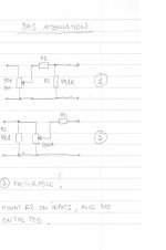
I have looked at the following two ways to do it (see picture), and think that number 2 must be the right one. As far as I remember Nelson used that principle on the B1 buffer also.
I have in mind to make mine as an integrated amp, and run the BA-3 from the same PSU as the F4.
The F4 will run nacked/crippled/liberated what ever people want to call it 🙂 Which means without the input buffer.
From experience be very carefull to set the F4 pots to the right value at startup 🙂
Best regards
Arthur.
congratulations to your decision about those builds 🙂
I am actually about to do the same, but I am still waiting for the BA-3 PCBs and some of the components to show up.
People tend to point to an Ernie Borbley paper about pot value, I think describing higher noise and a little bit narrower bandwith, by using higher value pots.
I have looked at the following two ways to do it (see picture), and think that number 2 must be the right one. As far as I remember Nelson used that principle on the B1 buffer also.
I have in mind to make mine as an integrated amp, and run the BA-3 from the same PSU as the F4.
The F4 will run nacked/crippled/liberated what ever people want to call it 🙂 Which means without the input buffer.
From experience be very carefull to set the F4 pots to the right value at startup 🙂
Best regards
Arthur.
Attachments
No.
The 2 version simply adds load to the output of the Pre.
It does not attenuate the excessive gain.
If you add a series resistor before the R2 then you create an extra stage of attenuation.
version 1 works as two stages of attenuation.
But why?
Why have so much gain that you have to install cascaded attenuation stages?
Maybe I am wrong, but I dont think the purpose is to attenuate the input signal, just to match the impedance better to reduce noise.
- Home
- Amplifiers
- Pass Labs
- BA-3 As Preamp