Hi, Patrick! Thanks for that!
I’ll be running standard 24v (22,5-ish under load). I have a 5U 400. Running 3 deep. But I have parts enough for 6 deep. So can’t rid myself of the urge to try 6 deep. I know I can use the 400 for that purpose, but I will be forced down on bias. Plus it would be really cool to have all 12 transistors in line 😀
I have been thinking about drawing a new mounting scheme and have Modushop drill it for me. They are based in Italy, so delivery is quite fast. I’ll check out Pico’s thread too.
Sorry to hear about fake fets 🙁 My source was out of them, I bought the last pairs. But if anyone can source them from Japan, he is your man.
I too wanted to build to spec. So after some searching and aggravation, Spencer had just sent me two matched pairs of K170/J74s @10mA iot bias the FE JFETs up to 8mA with original source resistance values.
Btw, I biased up the FE MOSFETs (Fairchild at the moment) to approx 60mA, and there was a siginifant difference in punch and dynamics. Worth a shot. What’s the status on your huge heatsink plan for the FE? I would like to try that, but not push the bias so much that I have to replace the source resistor values. Wanna experiment as little as possible with Nelsons resistor values... guess a tiny bit extra voltage drop is OK.
Cheers,
Andy
Hi guys!
So two of these are now in production at Toroidy, headed my way in a little while:
TTSA0300 - Transformer AUDIO TSA300VA - voltage to 50V - Shop Toroidy.pl
And then I removed the last bit of hum (more or less). It just took a bit of reduction in bias to more normal and safe levels. That, and following Bonsais advice, got me there in the end.
But well well, since they are on the way, I might as well start putting my new PSU plans into life: dual mono porn cap old-style/Choky-style PSU with big aluminium plates for the ground plane, and inductors... wish me luck! Double todays capacitance, inductors and shared load between two psu’s, and those transformers, make ripple a factor only relevant to my scope. I hope. 😀
Just waiting for Choky to approve the PSUD model. Hoping to get to it before come summer. We’ll see, playing nicely so no rush.
And Russel: I have done some thinking, usual OCD me. I guess differences between yours and mine build wrt hum and no hum, come down to some relevant factors:
1: Your tranny is bigger, badder and likely better than mine
2: you have 90kUf more capacitance for less load (you run lower bias than me).
But if yours is silent to 100db, well, I’ll be inspired. My first goal is 97db.
Cheers from corona-closed Norway!
Andy
Mine is quiet as the grave, unable to tell if its on quiet, even with the big Altec A7 speakers. They are over 100dB efficient.

The larger transformer likely does not help, It's quality does however. Raising lowering bias has no effect that I have noticed, but really haven't
played with it in that regard.
Your transformers should be excellent. I find noise and hum comes from how the amp is assembled, i.e. soldering and layout. A screwy power transformer can certainly raise these levels of hum.
Russellc
Last edited:
I know. Whatever the reason I have more noise than you, I’ll replace almost everything so gonna get there eventually. This time with the same FE transistors you used. Maybe the fire I had is the cause 🙂 Or a part is broken or a solder joint bad. I have basically given up finding the cause, and chose to replace most of the parts. It was a first build and had plenty of mistakes and so on.
Last edited:
It could just be the environment it is in, RF and so forth? Those transformer should be quiet, so if your layout is proper and I'm sure it is, I bet yours will be quiet.
Russellc
Russellc
I know. Whatever the reason I have more noise than you, I’ll replace almost everything so gonna get there eventually. This time with the same FE transistors you used. Maybe the fire I had is the cause 🙂 Or a part is broken or a solder joint bad. I have basically given up finding the cause, and chose to replace most of the parts. It was a first build and had plenty of mistakes and so on.
While it might not be the least expensive method, I agree. Certainly the best method to get proper sleep. When stumped, that is also my method as well!

You are hitting it with everything you have, you will get a good result for your efforts.

Russellc
Andy,
What heatsinks are you using for your FE Fairchild MOSFETS (Q3 and Q4)? Due to the configuration of the board, I just realized one can't easily mount the MOSFETS below the board to a custom heatsink, it is easier to be mounted above. Not to mention leaving enough space to allow convention to let the heat escape.
Thanks,
Anand.
Last edited:
Hi, Anand!
I am using the excact same sinks as 6L6 in the guide. I think they are from Avid, ordered from Mouser. I can get you the part number if you want, say so if so. They are a little bit bigger than the ones Nelson used in the manual.
You’re right, it could be done by mounting the MOSFETs under the board. My thought was, if I choose to bias a bit higher or just want more stable temp conditions for the MOSFETs, to cut a plate of aluminium to use as heatsink. I have seen some examples of that.
Cheers,
Andy
While it might not be the least expensive method, I agree. Certainly the best method to get proper sleep. When stumped, that is also my method as well!
You are hitting it with everything you have, you will get a good result for your efforts.
Russellc
Haha, agree, not the least expensive method. Though I kinda think you were right from the get-go, that my tranny might be the culprit. Have new parts, just gotta finish planning properly first.
Hitting it will all I’ve got, I think you are bloody right 😀
Hi, Patrick! Thanks for that!
I’ll be running standard 24v (22,5-ish under load). I have a 5U 400. Running 3 deep. But I have parts enough for 6 deep. So can’t rid myself of the urge to try 6 deep. I know I can use the 400 for that purpose, but I will be forced down on bias. Plus it would be really cool to have all 12 transistors in line 😀
I have been thinking about drawing a new mounting scheme and have Modushop drill it for me. They are based in Italy, so delivery is quite fast. I’ll check out Pico’s thread too.
Any time. Ah, I missed the switch to 24V rails in your thread. 😀
You should be able to run about the same Iq with the 5U/400 when compared to the 4U/500. The 5U has a tiny bit more total heatsink area, but at the expense of the overall length. However, you cannot fit two boards in-line in a 400mm deep chassis unless you get some custom boards made. See pic below for two store boards on top of a 400mm chassis. If you mean just running 6-deep (12-devices), yes, that can be done with the standard UMS on the 4U/500 using various mounting schemes. My personal favorite (that I have seen so far) is Itsmee's. Love to see your ideas.

Sorry to hear about fake fets 🙁 My source was out of them, I bought the last pairs. But if anyone can source them from Japan, he is your man.
Thanks. They came from a reputable seller, but ... oh well.
At last check, he was getting more. I'll reach out again to see if if he did.
I too wanted to build to spec. So after some searching and aggravation, Spencer had just sent me two matched pairs of K170/J74s @10mA iot bias the FE JFETs up to 8mA with original source resistance values.
Nice!
Btw, I biased up the FE MOSFETs (Fairchild at the moment) to approx 60mA, and there was a siginifant difference in punch and dynamics. Worth a shot. What’s the status on your huge heatsink plan for the FE? I would like to try that, but not push the bias so much that I have to replace the source resistor values. Wanna experiment as little as possible with Nelsons resistor values... guess a tiny bit extra voltage drop is OK.
Well, they're not "huge", but they're much larger than what I have, and I'll be putting a heat spreader between the two devices in an attempt to minimize offset and bias drift. The heatsinks on the current build are much too small, which was an error on my part. I have all the sinks and the heat spreader ready to go for when I get real Toshiba parts. I'll do that mod and put in the DIP switch for balanced operation all at once. I only want to remove and reinstall the boards once. 😀
Cheers,
Patrick
Interesting... wrt heatsink area. Iow, unless buying 5U 500, my chassis is just as good or better wrt dissipation. But boards need to be mounted in some nifty way.
I haven’t had time to check out Itsmee’s variant, but he is creative and seems to really know his stuff, so I’ll be inspired any day.
My solution is this, the best I’ve come up with so far:
1: Mount the first OS just like 6L6 in the guide, meaning fets on the bottom row.
2: The 5U heatsink has 6 additional fet holes, just above it’s vertical mid point. The top OS fet’s go there. Then, above these predrilled FET holes, there is plenty room for a second OS. Only thing needed is mounting holes, which have to be drilled with a certain degree of precision. That is where I am at. I have a possibly good solution, but need to get some tools and drill. Have a spare set of broken sinks to practice on.
This will be quite smooth, since both OS’es lay flat against the sinks and don’t take up too much space. Downside is the link wires between the boards need to be a few inches.
Btw where did you get your FETs, and how did you match them? What FETs did you choose? I have two sets from the store, and they are pretty close. But one of the N channels are off by 19% in current draw, so I am thinking I might wanna match some myself for the above installation.
Btw, nothing is decided. I am thinking a bit about this...
Regards,
Andy
What do you think?
Last edited:
Hi, Anand!
I am using the excact same sinks as 6L6 in the guide. I think they are from Avid, ordered from Mouser. I can get you the part number if you want, say so if so. They are a little bit bigger than the ones Nelson used in the manual.
Cheers,
Andy
Send me a link buddy! 🙂
Best,
Anand.
Hi Andy -
I definitely like your mounting solution. Itsmee's required no additional drilling for UMS ... so that's the way my lazy (fraidy-cat) self would have gone. The only (slight) downside is that the boards extend deeper into the amplifier chassis taking up some room. Your way seems very, very good, but yes, it will require some drilling and tapping if I understand you correctly.
I got two tubes (25 each tube) / 50 total N and P from Mouser. I matched for Vgs. Conditions were 0A5 24V after 30s. On a small heatsink. I used two heatsinks and swapped between them for each measurement to allow the heatsink to cool. However, I really don't think it was that critical. My measurement accuracy / precision is likely not good to 4 significant digits, but that's what I recorded.
N tube 1 - 4.097 to 4.172
N tube 2 - 4.281 to 4.419
All Ps were close enough to keep as one population - 4.290 to 4.314
I think you're well on your way to a really, really good amplifier. I also can't remember which thread you posted re: benefits of parallel devices with ZMs excellent reply. I also got a reply somewhere from Nelson himself when I asked a similar question re: number of devices / Iq etc. I was honored that he read my post and chose to respond. If I can find the exact post, I'll link it.
Not sure if you saw it, but I think I had posted somewhere my really long plans for my BA journey some time back. If you'd like it, and don't have it, I can repost or find the link. May give you some food for thought from a new guy. I was trying to work through the things like dissipation and planning for my PSUs etc. We seem to be on parallel (see what I did there? ) paths.
Cheers,
Patrick
I definitely like your mounting solution. Itsmee's required no additional drilling for UMS ... so that's the way my lazy (fraidy-cat) self would have gone. The only (slight) downside is that the boards extend deeper into the amplifier chassis taking up some room. Your way seems very, very good, but yes, it will require some drilling and tapping if I understand you correctly.
I got two tubes (25 each tube) / 50 total N and P from Mouser. I matched for Vgs. Conditions were 0A5 24V after 30s. On a small heatsink. I used two heatsinks and swapped between them for each measurement to allow the heatsink to cool. However, I really don't think it was that critical. My measurement accuracy / precision is likely not good to 4 significant digits, but that's what I recorded.
N tube 1 - 4.097 to 4.172
N tube 2 - 4.281 to 4.419
All Ps were close enough to keep as one population - 4.290 to 4.314
I think you're well on your way to a really, really good amplifier. I also can't remember which thread you posted re: benefits of parallel devices with ZMs excellent reply. I also got a reply somewhere from Nelson himself when I asked a similar question re: number of devices / Iq etc. I was honored that he read my post and chose to respond. If I can find the exact post, I'll link it.
Not sure if you saw it, but I think I had posted somewhere my really long plans for my BA journey some time back. If you'd like it, and don't have it, I can repost or find the link. May give you some food for thought from a new guy. I was trying to work through the things like dissipation and planning for my PSUs etc. We seem to be on parallel (see what I did there?
) paths.Cheers,
Patrick
A portion of the Toshiba devices I got to modify my input stage were likely fakes 🙁
That's really unfortunate. 🙁 What led you to that conclusion?
Thanks,
Dennis
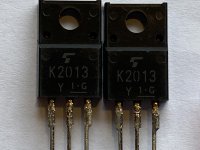
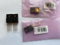
I wondered about the same thing. I can post a pic of mine tonight. They are not mounted so close-ups are easy. But I guess looks can deceive. Put my trust in my reliable source for now =) But good to know they are real before mounting. Desoldering those buggers is a pain.
Hi Andy -
I got two tubes (25 each tube) / 50 total N and P from Mouser. I matched for Vgs. Conditions were 0A5 24V after 30s. On a small heatsink. I used two heatsinks and swapped between them for each measurement to allow the heatsink to cool. However, I really don't think it was that critical. My measurement accuracy / precision is likely not good to 4 significant digits, but that's what I recorded.
N tube 1 - 4.097 to 4.172
N tube 2 - 4.281 to 4.419
All Ps were close enough to keep as one population - 4.290 to 4.314
I think you're well on your way to a really, really good amplifier. I also can't remember which thread you posted re: benefits of parallel devices with ZMs excellent reply. I also got a reply somewhere from Nelson himself when I asked a similar question re: number of devices / Iq etc. I was honored that he read my post and chose to respond. If I can find the exact post, I'll link it.
Not sure if you saw it, but I think I had posted somewhere my really long plans for my BA journey some time back. If you'd like it, and don't have it, I can repost or find the link. May give you some food for thought from a new guy. I was trying to work through the things like dissipation and planning for my PSUs etc. We seem to be on parallel (see what I did there?
Cheers,
Patrick
I think I read mot of it, but it’s lost now, somewhere in the build guide thread or the other one, BA-3 Burning amplifier or something. I’ll find it. But the inspiration/food has allready been consumated close to fully. Thank you!
Regarding the matching you did, I know you posted about that too. I’ll look it up. Of special importance is your jig. I have a perfect bench PSU for the purpose, and surplus sinks.
Question: you got 50 Ps and 50Ns, 100 in total? That was about my plan too.
Apparently, N-channel 240s may be more likely to misbehave than the P’s, according to something Sangram identified for me:
« And yes, the datasheet graphs between N and P will show you why the N devices are more affected by temperature - in the transfer functions, the Id comparison 25C vs 150C is about 5x at the same Vgs. For P channel devices, there is only about 2x difference.»
I am not going to pretend I understand all of that, but in conclusion the N’s may spread more easily than P’s. Certainly they seem to in my case (ref the discussion in the «BA-3 revisited» thread.
Cheers,
Andy
Last edited:
That's really unfortunate. 🙁 What led you to that conclusion?
Thanks,
Dennis
I will make the best attempt at fairness. I will also be intentionally vague to honor the seller. My claim of authenticity was immediately and fairly handled with a full refund even though I could not offer clear proof of "fake" parts. My position was (and is) that the onus was on the seller. My WAG is that they were a reseller vs. a company versed in the testing and knowledge of semiconductor parts. I consider it similar to purchasing tubes online. Many people have lots of tubes that to the best of their knowledge are authentic. Some do a limited amount of testing... many are purchased in bulk and resold. Some are NOS... some are not...
I cannot be 100% certain... I ordered both N and P channel parts. By my best (amateurish) determination...
For 1/2 my order:
1) The package structure did not match the Toshiba data sheet,
2) The package markings did not match the Toshiba data sheet, and
3) The "face" of the package seemed to have been cleaned and "re-etched"
I did not make anything other than very amateurish attempts to see how close the parts matched the performance of the specified parts. I did not want to potentially damage the parts since the seller agreed to a full refund.
It is important to note... the seller did not agree that my claims were accurate. They simply honored my request for return, which I felt was warranted. I may have returned perfectly good (and perhaps authentic) parts. I simply did not want to take the chance. The seller honored my request for return.
I think I read mot of it, but it’s lost now, somewhere in the build guide thread or the other one, BA-3 Burning amplifier or something. I’ll find it. But the inspiration/food has allready been consumated close to fully. Thank you!
Regarding the matching you did, I know you posted about that too. I’ll look it up. Of special importance is your jig. I have a perfect bench PSU for the purpose, and surplus sinks.
No, thank YOU for reading my nonsense. 😀 It's not really a jig. It's a bench supply, a couple resistors (big uns), a DMM, and a few heatsinks. It's not pretty, but it seems to have worked.
Question: you got 50 Ps and 50Ns, 100 in total? That was about my plan too.
Correct. I got Vishay parts. I later read that there may be some sort of misbehaving aspect to the Vishay parts vs. other manufacturers' versions of the same parts, but it has never given me a moment's pause... other than when audio nervosa kicks in.
My take is that if I can't understand why one part may be better than the other... I'll trust my ears... and I'm partially deaf anyway. 😀Apparently, N-channel 240s may be more likely to misbehave than the P’s, according to something Sangram identified for me:
« And yes, the datasheet graphs between N and P will show you why the N devices are more affected by temperature - in the transfer functions, the Id comparison 25C vs 150C is about 5x at the same Vgs. For P channel devices, there is only about 2x difference.»
I am not going to pretend I understand all of that, but in conclusion the N’s may spread more easily than P’s. Certainly they seem to in my case (ref the discussion in the «BA-3 revisited» thread.
I'll just nod and act like I understand. 😀 Kidding... but only a bit. I really am trying to learn how all this magic happens, but the simple fact is that I am proud to (sort of) even understand the behavior of an N channel vs. P channel part. It's a banner moment for me.
I truly appreciate your posts. Knowing that there are other curious minds out there that are just on the cusp of seeing behind the curtain is fun. I'm slow, slow, slow.... but when I can see other people's perspectives it helps me learn.
Plus, I really dig seeing new builds. The veterans are designing circuits. I'm still a solder-slinger.

I will make the best attempt at fairness. I will also be intentionally vague to honor the seller. My claim of authenticity was immediately and fairly handled with a full refund even though I could not offer clear proof of "fake" parts. My position was (and is) that the onus was on the seller. My WAG is that they were a reseller vs. a company versed in the testing and knowledge of semiconductor parts. I consider it similar to purchasing tubes online. Many people have lots of tubes that to the best of their knowledge are authentic. Some do a limited amount of testing... many are purchased in bulk and resold. Some are NOS... some are not...
I cannot be 100% certain... I ordered both N and P channel parts. By my best (amateurish) determination...
For 1/2 my order:
1) The package structure did not match the Toshiba data sheet,
2) The package markings did not match the Toshiba data sheet, and
3) The "face" of the package seemed to have been cleaned and "re-etched"
I did not make anything other than very amateurish attempts to see how close the parts matched the performance of the specified parts. I did not want to potentially damage the parts since the seller agreed to a full refund.
It is important to note... the seller did not agree that my claims were accurate. They simply honored my request for return, which I felt was warranted. I may have returned perfectly good (and perhaps authentic) parts. I simply did not want to take the chance. The seller honored my request for return.
Mine look like this, for comparison. Real or not, dunno. Look the part though =) Even looks like original Toshiba bags for the SJ’s.
Cheers,
Andy
Attachments
Hi Andy -
I definitely like your mounting solution. Itsmee's required no additional drilling for UMS ... so that's the way my lazy (fraidy-cat) self would have gone. The only (slight) downside is that the boards extend deeper into the amplifier chassis taking up some room. Your way seems very, very good, but yes, it will require some drilling and tapping if I understand you correctly.
Cheers,
Patrick
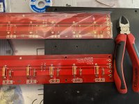
Here are two OS’es laid out on a surplus sink, in my intended way of mounting. As you can see, there is just enough room to clear the sink mounting brackets on the top portion of the sinks. Will require drilling and tapping of course, but seems a smooth way to do it.
Please disregard the messy OS, it is a discarded one that may or may not be used for testing purposes later =)
Cheers,
Andy
Attachments
- Home
- Amplifiers
- Pass Labs
- BA-3 Amplifier illustrated build guide