Hi Andy and ZM -
ZM - Thank you! I was absolutely scratching my head when looking at the article on the FW site vs. your referenced post. R8 and R9 in the article actually refer to R10 and R11. Making much more sense. I am still weakling re: actual circuit, but each day learning a bit more.
The FE bias doesn't drift too badly, I may just be worrying about nothing. It does stabilize after an hour or so. It is just challenging to get set within 5% on each side. It wanders about 5mA against a 45mA target when the lid comes off. The DC offset drifts 20-30mV immediately when the lid is off. Targeting 0V. I have it centered at about 8mV on one side and 6mV on the other.
First action will be larger heatsinks for Q3 and Q4 just to sleep better. They are really toasty, but not out of SOA. I think (as usual) that I am worried about nothing, but larger sinks will give those devices some help either way.
Andy - your observations and bias / offset plan are very similar to mine. I let it "cook" for about 2 hours initially or just wait for the meters to stabilize for small tweaks with the lid on. I use 6 meters for the front end (2x R10 2x R11 2x between "Top of R12" at C3 junction and GND). See pic. I use 4 for the output stage (2x at source resistor and 2x at output/GND)
I suppose I need 10 meters 😀
The output stage is absolutely rock stable. I can dial the bias to within a mA and null the offset to within 0.1 mV. Easy-Peasy.
Pics. Of course! Wanna see my kids? 😀 Here's BA-3 showing off. To the left is BJ2, and hiding shyly below BA-3 is Balanced Iron Pre. Current state of affairs after letting it sit over night at 0A4 bias per output device. Sinks are getting toasty, but not true burning amp toasty yet.
Thank you, gentlemen!


ZM - Thank you! I was absolutely scratching my head when looking at the article on the FW site vs. your referenced post. R8 and R9 in the article actually refer to R10 and R11. Making much more sense. I am still weakling re: actual circuit, but each day learning a bit more.
The FE bias doesn't drift too badly, I may just be worrying about nothing. It does stabilize after an hour or so. It is just challenging to get set within 5% on each side. It wanders about 5mA against a 45mA target when the lid comes off. The DC offset drifts 20-30mV immediately when the lid is off. Targeting 0V. I have it centered at about 8mV on one side and 6mV on the other.
First action will be larger heatsinks for Q3 and Q4 just to sleep better. They are really toasty, but not out of SOA. I think (as usual) that I am worried about nothing, but larger sinks will give those devices some help either way.
Andy - your observations and bias / offset plan are very similar to mine. I let it "cook" for about 2 hours initially or just wait for the meters to stabilize for small tweaks with the lid on. I use 6 meters for the front end (2x R10 2x R11 2x between "Top of R12" at C3 junction and GND). See pic. I use 4 for the output stage (2x at source resistor and 2x at output/GND)
I suppose I need 10 meters 😀
The output stage is absolutely rock stable. I can dial the bias to within a mA and null the offset to within 0.1 mV. Easy-Peasy.
Pics. Of course! Wanna see my kids? 😀 Here's BA-3 showing off. To the left is BJ2, and hiding shyly below BA-3 is Balanced Iron Pre.
Current state of affairs after letting it sit over night at 0A4 bias per output device. Sinks are getting toasty, but not true burning amp toasty yet.Thank you, gentlemen!
Nice, REALLY nice, work. Looks amazing. So guess you matched your own MOSFETs. Harris? And the case, is that 5u 500? And what type are those transformers?
Nice to hear I am not the only one toasting a bit, at 0,75 amps per device. 3 deep but still.
Nice to hear I am not the only one toasting a bit, at 0,75 amps per device. 3 deep but still.
Thank you very much! I am a bit ashamed re: 1) Wire dressing at I/O and entire back section. I thought I had it planned well, but... 2) Completely botched the holes for mounting the FE board to the back panel.
All will be fixed / tidied up.
Output devices are Vishay. I bought a few sleeves each of the 9240 and 240s about a year ago and tested them all at 0A5 for Vgs. I sorted and labeled them all for planned projects.
As an example, when I did the "3-deep" build, I knew I may want to try 6-deep and perhaps do balanced monoblocks. So, I sorted out 48 devices, marked them and set them aside. I haven't measured across all the source resistors yet to see if there are any little piggies trying to hog current, but all the Ns are matched to within ~0V06 (4V097 to 4V156) and the Ps were incredible out of the tube and are within ~0V01 (4V290 to 4V303). My matching technique probably has a bit of error, so I probably should be clear that those were my measurements... any may not be completely accurate. I was consistent and used heatsinks, so the delta between them is probably pretty solid (decent precision), but the actual Vgs may be off a touch.
The chassis is Pico's Toxic Masculinity 4U/500. The BJ2 is in a 5U/400 to the left for comparison.
In preparation, I biased the "3-deep" up to 1A0 in the 5U/400 to see how burning I dared go into burning amp territory. 🙂
Wish I could help re: your previous question. I'll noodle over it. I saw the same thing in the article, but was too much of a chicken to measure mine and compare to the 8mA target. It's a great thought. I have to take the FE boards out eventually to mod them for balanced... so.... You're a bad, bad man for putting that thought into my head.
Edited: Corrected chassis dimensions.
Last edited:
Time for some fundamentals again. I've read and read since I started DIY, but some things just haven't quite "clicked". There are wonderfully kind people out there that would probably answer this privately and walk me through it. However, by posting this, it may benefit someone else that just can't quite put their finger on it.
One of my goals, however foolish, was/is to set up the BA-3 to deliver all of its available power in Class-A with no "klunk" while also trying to balance the rails / quiescent current / dissipation for a speaker load between 4 and 16 ohms.
I thought that was somewhat reasonable. I had no particular maximum power targets in mind, I just wanted to balance things out to the best of my abilities.
P=Vrms^2/Rload
Rload varies between 4 and 16
For a complimentary, non-bridged output: V = rails, correct? Each device can swing to each rail relative to GND.
...
P=23^2/4 = 132W
P=23^2/16 = 33W
If I read correctly, the gain of the BA-3 front-end is ~30x. I should have underlined and bolded that in my notes...
So, the input sensitivity would be 23V/30 => 0V77, correct?
My current settings are 0A4 across each output device * 12 devices * 23V => ~110W dissipation.
If I wanted (however silly it might be) no "klunk" with 23V rails into 4 ohms, I would up my quiescent current to 132/12/23 => ~0A5 rounding up per device. Correct?
If, for some reason I wanted higher power into 16 ohm loads, I'd need to go higher on the rails (or go balanced/bridged), is that correct?
For balanced/bridged, the voltage per "phase" remains the same, but now I've got the capability to swing between the rails instead of from one rail to GND, correct? So 46V of swing?
So, for one channel...
P=46^2/4 => 529W
P=46^2/16 => 132W
However, with the 4ohm load... W=VA 529 / 46 => I need 11A5 of available quiescent current to not "klunk"... but 0A5 ish * 24 (not 12) => 12A from previous math. So, I think all would be good.
Where I think I'll do a modification is to up the rails or lower the gain (if practical). An input sensitivity of 0V77 if I've calculated it properly is too low. I would worry that some numpty (like me) would accidentally drive the amp to clipping and cause speaker or amplifier damage if the "volume knob" on a pre-amp that can reliably put out 5V in balanced was left too high. Plus, I'm throwing away perfectly good gain.
Am I nuts? Ok, don't answer that... but any thoughts, corrections, critiques would be most greatly appreciated as always.
I also know that I'll never use the amp(s) to their full capability. This is DIY, fun, and learning. I'll never need 500W into 4 ohms or even a fraction of that, but it sure is fun to think about.
Thanks again in advance for anyone willing to read through the "wall of text" and help a fella out.
Darn it!
I have at least one or two fundamental errors... DOH!
Error 1 - I can't swing to the rails b/c I lose a bit of voltage across the source resistors. I've seen that to be estimated ~2V. My source resistors are 0R22. If there is a more accurate calc, then I'm willing, but I don't think it's as simple as just using ohm's law... or is it?
So output devices can swing to +21V / -21V =>42V pk to pk
Error 2 -
P=Vrms^2/Rload
Vpk to pk * 0.707 => Vrms
Vrms = 42*0.707 = 30Vrms rounded
Did I get that right? If so, I can move along... once again.
Last edited:

As usual, MANY thanks to you both.
Moving along from getting some essentials close enough for estimates, I have done a few hours more reading and moving through other threads and previous notes along with re-reading this thread again... 🙂
For normal stereo, non-bridged/balanced operation. Complimentary. 6-pairs per channel.
I can swing between +21V and -21V relative to GND at the speaker outputs. Each speaker could "see" up to +21V or -21V. That's 42Vpp => 30Vrms
Onward ...
30Vrms^2 / 4 = 225W
30Vrms^2 / 8 = 112W
30Vrms^2 / 16 = 56W
Assuming driving the amp to voltage clipping into the load, what Iq is needed to remain in class-A operation under a particular load? Clipping by definition would occur at 21Vpk (or -21Vpk)
I=Vpk/R
21/4 = 5A3
21/8 = 2A6
21/16 = 1A3
Here's where I get a bit lost again... of course.
Assuming 0A5 per device and referencing ZMs exceptional graphic back in post #293...
6 pairs at 0A5 => 1A of current per pair in class-A operation => 6A per side. Is that the way to think of it?
So, this amp will reach voltage clipping w/o leaving Class-A operation with a bit of room to spare. If the speakers dip to 2ohm ... well, I'm still probably not listening loudly enough for them to ever leave Class-A.
Did I get it, correct? If so, then hallelujah!!!
Onward again!
Bridged / Balanced - Sadly, I thought I had it correct, but I'm now confused. Shocking! See if this is correct, please.
I think I fundamentally understand what the voice coil sees as the voltage differential between the two speaker outputs in balanced/bridged operation vs. one output and GND for non-bridged. Please give me a sanity check.
Conversely...
Therefore... if I have it correct.
Vpp for the bridged amp => 84V
225W => 16ohm
450W => 8ohm
900W => 4ohm
That seems utterly insane. 😱 What'd I do wrong?
This all ties back to my post #284 in May and some of the goals I set earlier for the "grand BA plan". I'm slow, but I might eventually get there.
I read a bunch of other posts, specifically noting Generd's and Botte's work, where measured gain was closer to 8.5x. 21/8.5 => 2V5 input sensitivity makes me much more comfortable. I have the ability to measure the gain, so I will. I can't figure out all the calculations, and if the venerable AndrewT (RIP) had questions, then I likely won't figure it out. Just measure it. 😀
AND for those of you that made it this far; you're saints.
Moving along from getting some essentials close enough for estimates, I have done a few hours more reading and moving through other threads and previous notes along with re-reading this thread again... 🙂
For normal stereo, non-bridged/balanced operation. Complimentary. 6-pairs per channel.
I can swing between +21V and -21V relative to GND at the speaker outputs. Each speaker could "see" up to +21V or -21V. That's 42Vpp => 30Vrms
Onward ...
30Vrms^2 / 4 = 225W
30Vrms^2 / 8 = 112W
30Vrms^2 / 16 = 56W
Assuming driving the amp to voltage clipping into the load, what Iq is needed to remain in class-A operation under a particular load? Clipping by definition would occur at 21Vpk (or -21Vpk)
I=Vpk/R
21/4 = 5A3
21/8 = 2A6
21/16 = 1A3
Here's where I get a bit lost again... of course.
Assuming 0A5 per device and referencing ZMs exceptional graphic back in post #293...
6 pairs at 0A5 => 1A of current per pair in class-A operation => 6A per side. Is that the way to think of it?
So, this amp will reach voltage clipping w/o leaving Class-A operation with a bit of room to spare. If the speakers dip to 2ohm ... well, I'm still probably not listening loudly enough for them to ever leave Class-A.
Did I get it, correct? If so, then hallelujah!!!
Onward again!
Bridged / Balanced - Sadly, I thought I had it correct, but I'm now confused. Shocking! See if this is correct, please.
I think I fundamentally understand what the voice coil sees as the voltage differential between the two speaker outputs in balanced/bridged operation vs. one output and GND for non-bridged. Please give me a sanity check.
The board for the non-inverted signal reaches a voltage peak of +21V relative to GND.
The board for the inverted signal will simultaneously produce -21V relative to GND.
The speaker reacts to the differential of +42V (when wired normally for bridged operation).
The board for the inverted signal will simultaneously produce -21V relative to GND.
The speaker reacts to the differential of +42V (when wired normally for bridged operation).
Conversely...
The board for the non-inverted reaches a voltage peak of -21V relative to GND.
The board for the inverted signal will simultaneously produce +21V relative to GND
The speaker reacts to the differential of -42V (when wired normally for bridged operation).
The board for the inverted signal will simultaneously produce +21V relative to GND
The speaker reacts to the differential of -42V (when wired normally for bridged operation).
Therefore... if I have it correct.
Vpp for the bridged amp => 84V
225W => 16ohm
450W => 8ohm
900W => 4ohm
That seems utterly insane. 😱 What'd I do wrong?
This all ties back to my post #284 in May and some of the goals I set earlier for the "grand BA plan". I'm slow, but I might eventually get there.
I read a bunch of other posts, specifically noting Generd's and Botte's work, where measured gain was closer to 8.5x. 21/8.5 => 2V5 input sensitivity makes me much more comfortable. I have the ability to measure the gain, so I will. I can't figure out all the calculations, and if the venerable AndrewT (RIP) had questions, then I likely won't figure it out. Just measure it. 😀
AND for those of you that made it this far; you're saints.
Last edited:
As usual, MANY thanks to you both.
Moving along from getting some essentials close enough for estimates, I have done a few hours more reading and moving through other threads and previous notes along with re-reading this thread again... 🙂
For normal stereo, non-bridged/balanced operation. Complimentary. 6-pairs per channel.
I can swing between +21V and -21V relative to GND at the speaker outputs. Each speaker could "see" up to +21V or -21V. That's 42Vpp => 30Vrms..............
from now on, you can share a nickname with Mighty Moi - Schopenhauer ........ mightyyyyyyyyy impressive building you have, only foundation made of glass

42V(pp) voltage envelope ........ divide with 2 , you get Vp ........... divide with 1.41, you get Vrms
so 42Vpp = 14.85Vrms
Well, DRAT! Total dodoness. 
I did Vpp/2*1.414
It's now locked into my spreadsheet never to be touched again.
I will need to research Schopenhauer, but sharing any nickname with you is an honor.
The good news (regardless of total watts for bragging rights) is that I still have more than enough voltage swing to the speakers for delighting myself and scaring the neighbors. I have enough Iq to never leave the "Class-A envelope" up to clipping (except below 4ohm loads).
I know that the "klunk" is not a big thing, but it was a goal and a way to learn. So, I am very happy.
Corrected calcs and summary below... Rounding to 15Vrms.
Standard Stereo
15Vrms^2 / 4 = 56W
15Vrms^2 / 8 = 28W
15Vrms^2 / 16 = 14W
Balanced / Bridged
Vpp for the bridged amp => 84V
30Vrms^2 / 4 = 225W
30Vrms^2 / 8 = 112W
30Vrms^2 / 16 = 56W
Edited to add - AND most importantly, it sounds flipping fabulous! 😀
Last edited:
well, to be frank, I'm thinking in Xpp domain always, and having if not difficulties, then PITA feeling - each time when I must recalc something to Xp or Xrms
anyway. I'll try to decipher current domain, you you can think how much of KlunK! you can allow
say that you have 24 rails
voltage envelope is 48Vpp
cut for losses few volts, so you're around 44-45Vpp
output can go in one direction half of that ......... and that's what Pa is often citing as Vp (peak voltage), being extremely successful in making Poor ZM feeling even more inadequate
anyway, that Vp thingie is good ( in my brain) just for one thing - you can calculate what's peak current though load .... peak current though load is greatest in moment when you push max voltage through same ..... so, say 22V5 divided with 8R, gives you 2.8125A
I linked here pic from post you mentioned, so you can see that Iq of OS need to be half of Peak Current (edit: when dealing with wimpy made output stages, having local degeneration; take PL XA25, which is not having that, and throw all this calculus through window, at least when speaking about defining KlunK! point)
now, you can do simple math for any load you intend to burden your Sissy amp with, so you can make some plans - how much of heatsinking, and Watts in Donut and Farrads in cans and number of output devices you think to mess with
simple, isn't it ......... and people are talking that amp construction is for professionals
suckers!
Last edited:
😀
I like the idea of working "backwards" from the goals. I totally agree. This was my first attempt at modifying an amp just a tiny bit for me. Since I don't build commercial amps for people with all kinds of speakers, I can set mine up best for me.
I tried to work backwards on a plan for keeping the amp in Class A, but w/o adding unnecessary heat from higher rails. I don't need the voltage. I wanted more Iq, but maybe I did not need it.
Excellent! That's where my head was when calculating how much peak current was needed at clipping (21Vp / 4R => 5A25 Ip) for my speakers.
Thank you! Let's keep it easy. I won't try to build an XA25 clone.
Before, I had the AHA and understood the simple concept that during "handoff" both devices in push-pull are still working. That was a big understanding.
Taking it further. It looks like R1 and R2 would be the source resistors for a complimentary pair. Current through them blue and green. Red is current through load, which looks like noted as 4R.
The current through R1 and R2 would be Ip of 4A and Ipp of 4A, correct?
The current through load would be Ip of +- 4A with Ipp of 8A. Is that correct?
I also get confused when we "add pairs" in parallel for a complimentary system. I have 6 pairs. 6N and 6P.
This is where I get lost.
Each source resistor is at 0A5 Iq. So, I can have 1A0pp current per pair in Class-A, correct?
We sum the current for the pairs vs. individual devices, correct? I can have each green and blue line go 0A to 3A. The red line can go +3A -3A.
So, I would have 6App available before leaving Class-A, if I got that part right.
If 21Vp/4R => 5A25 Ip required, correct? So, I am not having enough Iq???
But that does not agree with 5A25 / 2 => 2A125
Do I only need current at each source resistor to be 2A125 / 6 to maintain class-A at 21V / 4R?
Maybe time to give the brain a rest and look again after some food.
As always, thank you!!!!
😕
now, you can do simple math for any load you intend to burden your Sissy amp with, so you can make some plans - how much of heatsinking, and Watts in Donut and Farrads in cans and number of output devices you think to mess with
simple, isn't it ......... and people are talking that amp construction is for professionals
suckers!
I like the idea of working "backwards" from the goals. I totally agree. This was my first attempt at modifying an amp just a tiny bit for me. Since I don't build commercial amps for people with all kinds of speakers, I can set mine up best for me.I tried to work backwards on a plan for keeping the amp in Class A, but w/o adding unnecessary heat from higher rails. I don't need the voltage. I wanted more Iq, but maybe I did not need it.
anyway. I'll try to decipher current domain, you you can think how much of KlunK! you can allow
say that you have 24 rails
voltage envelope is 48Vpp
cut for losses few volts, so you're around 44-45Vpp
output can go in one direction half of that ......... and that's what Pa is often citing as Vp (peak voltage), being extremely successful in making Poor ZM feeling even more inadequate
anyway, that Vp thingie is good ( in my brain) just for one thing - you can calculate what's peak current though load .... peak current though load is greatest in moment when you push max voltage through same ..... so, say 22V5 divided with 8R, gives you 2.8125A
Excellent! That's where my head was when calculating how much peak current was needed at clipping (21Vp / 4R => 5A25 Ip) for my speakers.
I linked here pic from post you mentioned, so you can see that Iq of OS need to be half of Peak Current (edit: when dealing with wimpy made output stages, having local degeneration; take PL XA25, which is not having that, and throw all this calculus through window, at least when speaking about defining KlunK! point)
Thank you! Let's keep it easy. I won't try to build an XA25 clone.
now, you can do simple math for any load you intend to burden your Sissy amp ...
simple, isn't it
Before, I had the AHA and understood the simple concept that during "handoff" both devices in push-pull are still working. That was a big understanding.
Taking it further. It looks like R1 and R2 would be the source resistors for a complimentary pair. Current through them blue and green. Red is current through load, which looks like noted as 4R.
The current through R1 and R2 would be Ip of 4A and Ipp of 4A, correct?
The current through load would be Ip of +- 4A with Ipp of 8A. Is that correct?
I also get confused when we "add pairs" in parallel for a complimentary system. I have 6 pairs. 6N and 6P.
I linked here pic from post you mentioned, so you can see that Iq of OS need to be half of Peak Current
This is where I get lost.
Each source resistor is at 0A5 Iq. So, I can have 1A0pp current per pair in Class-A, correct?
We sum the current for the pairs vs. individual devices, correct? I can have each green and blue line go 0A to 3A. The red line can go +3A -3A.
So, I would have 6App available before leaving Class-A, if I got that part right.
If 21Vp/4R => 5A25 Ip required, correct? So, I am not having enough Iq???
But that does not agree with 5A25 / 2 => 2A125
Do I only need current at each source resistor to be 2A125 / 6 to maintain class-A at 21V / 4R?
Maybe time to give the brain a rest and look again after some food.
As always, thank you!!!!
😕
re-read few times what I wrote, then try to imagine what I forgot to wrote
simple as this :
maximal current you can get in load is one rail voltage divided with Rload, not counting losses in source resistor and transistor itself (Rdson)
to avoid KlunK! , your Iq needs to be at least half of previously calculated current (Ipeak)
sum Iq is divided by number of vertically looking/oriented pairs, simply because that is current path - vertical
so, it's simple - you know sum Iq, divide it with number of pairs, you have Iq per pair, divide with 2 and multiply with rail V, you have dissipation per part
simple math, imagine apples or oranges or marbles, same thing
please, do not confuse me further with Xpeak related questions, while I just got (right I hope) relation between Xpp and Xrms
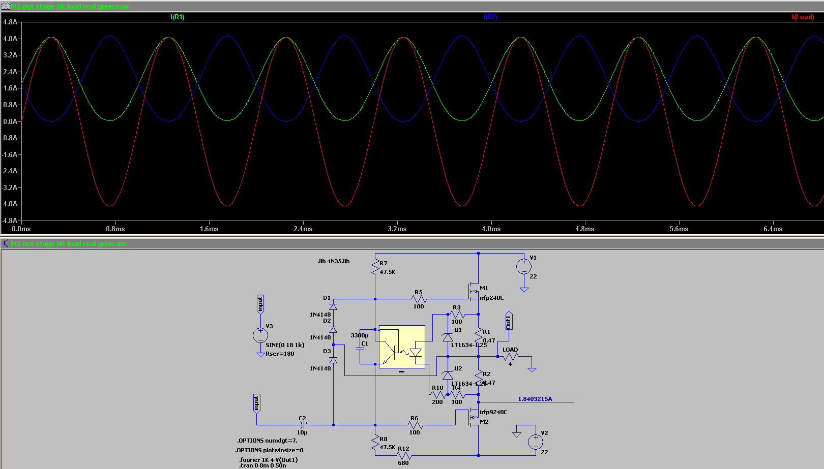
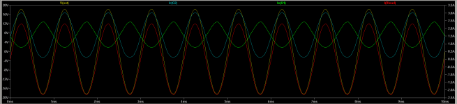
just to illustrate fact how things are simple, here is sshot from sim of amp I'm recently working on
(current through upper device, current through lower device, current through Rload, voltage across Rload)
prototype measurements are confirmative
rails are sorta 22-23Vdc, Iq 1A5, no emiter resistors (yup, bips in OS, shoot me)
I need to find math model for prediction of that (KlunK!), but I'm neither Pa (replaced math with mileage) nor lhquam (all math which I'm not even capable to imagine), but I think that I'll stay with sims and measurements
prediction is, anyway, for Sissies
Attachments
This is brilliant! Thank you. A few hours for me to rest the brain also helps. 🙂
From #714, I previously got it right from intuition that max current (Ipeak) will be from one rail. 😀 It makes perfect sense to include the loss from the device Rdson and the source resistor (if used) to get true Vpk from rail. I never considered the loss from the transistor.
#715 and previous graphs from early posts in May with new explanation help tremendously.
Noticing your new graph, each part in the vertical pair doesn't even have to pass equal current.
I don't need to know the math like Lynn, and I will never have the experience of Papa. I respect all approaches. As a padawan, I like to learn general concepts that apply in most situations and see if my wee brain can comprehend.
Observations
I finally just picked up that the Iq (since the devices are always on and passing current) is the starting point or (not sure of correct term) zero crossing vs. 0A.
Am I looking properly at the graph in #715? It seems one device (Q2) is working a bit harder than the other. Q1 is 1A5 Iq with swing of ~+-1A. Q2 is providing more ooomph or passing more current at the same voltage. 1A5 Iq with swing ~+-1A5. Could that be because of different Ice?? You have c and e in the graph and mention emitter resistors... so assuming collector and emitter in this case. I just don't know equivalent term for Ids for something with collector and emitter. I admit to a bit of guessing, but trying to exercise the brain and show a bit of thought since you put in so much effort to teach.
Interpreting what you didn't type - 😉
In this case, if I understand properly, Vpk is ~18V. Ipk with 6R will be 3A. 3A/2 => 1A5 Iq
Working backwards designing an amp to work well with normal 4 to 8 ohm speakers... Class A to Vpeak of 18V into 6R load => 1A5 Iq Little lower "Class-A power" into 4 ohms.
If I only had one vertical pair 1A5 Iq is the set point. If I had two vertical pairs 0A75 for each would be the set point.
Maybe?
--------------
My case -
If I finally understand and have it right, below should be proper way to determine Iq for my rails and preserving no "klunk" up to clipping into 4R.
21Vp / 4R => Ip 5A25
6 vertical pairs
5A25 / 6 => 0A875 per pair => 0A438 per device.
OR22 source resistors => Target 96mV across source resistors give or take.
Voila! 😀

A few hours for me to rest the brain also helps. 🙂From #714, I previously got it right from intuition that max current (Ipeak) will be from one rail. 😀 It makes perfect sense to include the loss from the device Rdson and the source resistor (if used) to get true Vpk from rail. I never considered the loss from the transistor.
#715 and previous graphs from early posts in May with new explanation help tremendously.
Noticing your new graph, each part in the vertical pair doesn't even have to pass equal current.
I don't need to know the math like Lynn, and I will never have the experience of Papa. I respect all approaches. As a padawan, I like to learn general concepts that apply in most situations and see if my wee brain can comprehend.
Observations
I finally just picked up that the Iq (since the devices are always on and passing current) is the starting point or (not sure of correct term) zero crossing vs. 0A.
Am I looking properly at the graph in #715? It seems one device (Q2) is working a bit harder than the other. Q1 is 1A5 Iq with swing of ~+-1A. Q2 is providing more ooomph or passing more current at the same voltage. 1A5 Iq with swing ~+-1A5. Could that be because of different Ice?? You have c and e in the graph and mention emitter resistors... so assuming collector and emitter in this case. I just don't know equivalent term for Ids for something with collector and emitter. I admit to a bit of guessing, but trying to exercise the brain and show a bit of thought since you put in so much effort to teach.
Interpreting what you didn't type - 😉
In this case, if I understand properly, Vpk is ~18V. Ipk with 6R will be 3A. 3A/2 => 1A5 Iq
Working backwards designing an amp to work well with normal 4 to 8 ohm speakers... Class A to Vpeak of 18V into 6R load => 1A5 Iq Little lower "Class-A power" into 4 ohms.
If I only had one vertical pair 1A5 Iq is the set point. If I had two vertical pairs 0A75 for each would be the set point.
Maybe?
--------------
My case -
If I finally understand and have it right, below should be proper way to determine Iq for my rails and preserving no "klunk" up to clipping into 4R.
21Vp / 4R => Ip 5A25
6 vertical pairs
5A25 / 6 => 0A875 per pair => 0A438 per device.
OR22 source resistors => Target 96mV across source resistors give or take.
Voila! 😀
So with 4ohm speakers a huge chassis BA-3 or the F5T are the way to go... ai don’t have a huge chassis. So I should either swap speakers or but my Fairchilds and Turbo boards to use...
......
My case -
If I finally understand and have it right, below should be proper way to determine Iq for my rails and preserving no "klunk" up to clipping into 4R.
21Vp / 4R => Ip 5A25
6 vertical pairs
5A25 / 6 => 0A875 per pair => 0A438 per device.
OR22 source resistors => Target 96mV across source resistors give or take.
Voila! 😀
View attachment 931196
all (mostly) good, up to the end
hold your horses for a moment
imagine output stage with just one pair
Iq is, say, 2A
these two transistors ( mosfets, bjts, JFets, whatever) are forming sole vertical current path, so you'll have 2A per device
dissipation per device is Iq ( again - 2A) mult. with voltage across same device , which is value of one rail
double number of outputs
current is then divided between two vertical path, so each vertical path is conducting 1A
dissipation per device is then Iq/device mult. with voltage ( one rail)
so, when you go backwards , things are simpler than you getting it
sum dissipation is overall Iq mult. with sum voltage ( sum of two rails)
then dissipation per device is simply sum dissipation divided with total number per devices
while current through each device is sum Iq divided with number of vertical pairs
whichever direction you go, to calc dissipation per device, you'll get same number
pair of devices is vertical pair , from two reasons: usually you have one P and one N, so you can see it as that - PN pair......... or you can look at neighbor/adjacent parts or - most proper way of look : one member of one pair is situated on one rail, second member of same pair is situated on adjacent/second rail
so, to qoute and edit what you wrote :
21Vp / 4R => Ip 5A25
6 vertical pairs
Iq = 5A25 / 2 => 2A625
sum Iq/number of pairs = Iq/pair/device=0A4375
OR22 source resistors => Target 96mV across source resistors give or take.
(that last you got right , target 96mV, but with totally wrong and twisted approach
)so , dissipation is both rails ( 45Vdc?) mult. with sum Iq
so let's say it is 45V x 2A625 = 118.125W
dissipation per device is simply 118.125/(6x2)pieces=9.84W
so, think - it's really simpler than you're making it
Well, I did admit to being a numpty. Some sleep, more reading, some good coffee, more reading, some picture drawings...
NOW, I actually understand vs. just getting the answer correct.
These things finally got my brain to click.
--------------------
So is it correct below with a few added words for clarification? It helps me to go backwards and forwards. If I had an unknown stereo BA-3 on my bench that someone else set up, and I wanted to know a few key things ...
Observe and note total number of vertical pairs - 3
Measure voltage of loaded rails - 24V
Check source resistor value - OR47
Measure voltage across source resistors - 0V235
Heat load / dissipation
Heat load uses full rails b/c that's what gets dissipated through the transistors.
Dissipation => 0V235 / 0R47 => 0A5*6*24 =72W
Checking within recommendations not greater than 35W. Dissipation per Device => 12W OK
How much POWER!?
Assume 2V loss from rails due to Rdson, source resistors, and other loss that is dissipated, but "got lost in heat". No contribution to power, but can keep the room warm.
0A5 at each device * 3 vertical pairs => Iq => 1A5
Ipk => 3A
22V
3A*22V => 66W would be peak power in Class-A into some load.
What nominal speaker impedance would be "best" to use all that power all the way to voltage clipping?
22V/3A = 7R33
If I want higher class-A power into higher impedance, increase rails.
If I want higher class-A power into lower impedance, increase total Iq => Ipk either through increasing bias current per device or by adding pairs.
As always, a heartfelt thank you! Yes, it is simple, but until the brain "clicks"...
Some sleep, more reading, some good coffee, more reading, some picture drawings...NOW, I actually understand vs. just getting the answer correct.
These things finally got my brain to click.
1) "Iq is, say, 2A... these two transistors ( mosfets, bjts, JFets, whatever) are forming sole vertical current path, so you'll have 2A per device."
2) "- most proper way of look : one member of one pair is situated on one rail, second member of same pair is situated on adjacent/second rail"
I knew this b/c that's how the devices work, but for some reason my brain got stuck when trying to fit all the pieces of the puzzle together at once to form the full picture.
3) "Iq = 5A25 / 2 => 2A625
sum Iq/number of pairs = Iq/pair/device=0A4375"
I was using the wrong terms. Noted - 5A25 should be Ipk not Iq.
I think I have it now.sum Iq/number of pairs = Iq/pair/device=0A4375"
I was using the wrong terms. Noted - 5A25 should be Ipk not Iq.
--------------------
So is it correct below with a few added words for clarification? It helps me to go backwards and forwards. If I had an unknown stereo BA-3 on my bench that someone else set up, and I wanted to know a few key things ...
Observe and note total number of vertical pairs - 3
Measure voltage of loaded rails - 24V
Check source resistor value - OR47
Measure voltage across source resistors - 0V235
Heat load / dissipation
Heat load uses full rails b/c that's what gets dissipated through the transistors.
Dissipation => 0V235 / 0R47 => 0A5*6*24 =72W
Checking within recommendations not greater than 35W. Dissipation per Device => 12W OK
How much POWER!?
Assume 2V loss from rails due to Rdson, source resistors, and other loss that is dissipated, but "got lost in heat". No contribution to power, but can keep the room warm.
0A5 at each device * 3 vertical pairs => Iq => 1A5
Ipk => 3A
22V
3A*22V => 66W would be peak power in Class-A into some load.
What nominal speaker impedance would be "best" to use all that power all the way to voltage clipping?
22V/3A = 7R33
If I want higher class-A power into higher impedance, increase rails.
If I want higher class-A power into lower impedance, increase total Iq => Ipk either through increasing bias current per device or by adding pairs.
As always, a heartfelt thank you! Yes, it is simple, but until the brain "clicks"...
Last edited:
here:
Dissipation => 0V235 / 0R47 => 0A5*6*24 =72W
result and calculus is OK, but logic isn't, for principle sake
it should be :
Dissipation => 0V235 / 0R47 => 0A5*3 current vertical paths (each carrying 0A5) * (24Vdc *2) =72W
in some cases , keeping with principle can save you from omissions
been there, done that ..... when working on some gargantuan amp for customer, mistakes can cost you entire pre-arranged fee
had some monsters for repair, with 1KW5 Donuts and drekload of Hitachi T03 mosfet cans
boy, that was some wrestling, not just because of weight (couldn't lift it alone on the bench)
Last edited:
So you braindudes keep doing math. But sticking with simple principle. One either needs sissy amp for sissy speaker load, or muchos ampos for low impedance non sissy speaker, to stay in class A.
We have plenty choice on the low power side, and the F5T and BA-3 six deep huge chassis on the non sissy side. One one of them has a blow-up inclination, but a cool challenge for sure.
But what about those XA incarnations of yours? How many String Emil style photos of myself must I publish to earn some of those boards? Or maybe Babelfish?
Or maybe be happy with what I have, hehe.
But seriously: great stuff, guys! A real learning experience reading, really cool. I will implement in future projects!
ZM: can you shed some more light on PSU calculations wrt capacitance? Dissipation vs tranny I am comfy with allready. Ripple vs cmrr, ripple vs current draw, etc. how to land it!
Also, 8 ohms is the go to for most of these amps. I get the challenges wirh lower impedances as well as impedance swings, requiring ampos for the first and wattage for the second.
But what about 12 ohm speakers? Any challenges there? Higher rail voltage a must? What about resistors across speaker terminals? ZM can you shed some light on it? Did not find much in the forum, but perhaps I did a crappy search.
Cheers.
Andy
Last edited:
- Home
- Amplifiers
- Pass Labs
- BA-3 Amplifier illustrated build guide