I doubt the pot matters, they will eventually be adjusted anyway, well if you plan on going that far with it.
I used those same heatsinks, I do believe they float above the board. I cant remember right now if the back sides of those FE mosfets are conductive or not, but if so and you are worried about it you could use an insulator for it. Seems like I remember those small mosfets not having conductive backs...its been a while.
The hole in the mosfet and the hole in the heatsink line up to leave it proud of the board IIRC.
Russellc
The small diff in the trimmer for P3 won't matter. As a first step, before installation,
you should adjust the pots so the two halves have equal resistance.
If the heatsinks can rest on the pcb with the mosfet attached to one of the mounting
holes then I would keep it on the PCB for support. The original Toshiba mosfets
have insulated tab and back. If you're using the Fairchild mosfets then you can
always add TO220 silpads and insulators.
Thanks, guys! I actually ordered insulators for the Fairchilds, but now i cant find them. Argh. Anyways, my heatsinks turned out to be too wide and will interfere with R13. Any of you remembwr the part number for those hestsinks you (Russel) and 6L6 used? Mounted 4 out of 6 pots tonight, now take care of the missus =)
Last edited:
The heatsink shown on page 1 of the build guide appears to be this:
https://www.mouser.ca/ProductDetail...=/ha2pyFadugpge1dGluweDJ2DvcDZehkralshEOkxSM=
https://www.mouser.ca/ProductDetail...=/ha2pyFadugpge1dGluweDJ2DvcDZehkralshEOkxSM=
Fantastic. Thanks!
Bought Keraterm insulatoes from the store. They don’t fit TO-220 and have to be cut to size. What are tour thoughts on these? I saw a statement from Nelson on silpads, and he chose to use goo with them too as thermal stability was better sith than without. According to him, heat dispersed more evenly across the sinks. But the Keraterms are stated explicitly not to be used with goo.
Regards,
Andreas
The heatsink shown on page 1 of the build guide appears to be this:
https://www.mouser.ca/ProductDetail...=/ha2pyFadugpge1dGluweDJ2DvcDZehkralshEOkxSM=
That is it. Good eye.
Russellc
So I’ll soon be finishing the front end. I have a question regarding caps. I bought som big Vishays for C3. Should I put in some small silmics as well, or can i just leave small C3 spot completely open and unused? Nelson did this in the depicted board in the BA-3 manual. Reason I ask is because I see people bypass the big C3, for example 6L6. Why? Does it mean that you can leave the small C3 spots unused, but not the big ones? I also bought bypass caps, so have several options. I also have small Nichicons I can use. But need your advice here.
Regards,
Andreas
Regards,
Andreas

Fantastic. Keraterm
If you search for the respective product sheets, you will see that keratherm has one of the best thermal resistance of all those materials.
There‘s some carbon-stuff from Panasonic which is way better, but they are conductive...
Another question is whether such high-performance pads aren‘t overshooting.
Hello andynor,
I would use an filmcap with around 10µF. But you can also use a bipolar.
Some use bipolars and bypass with a small filmcap.....
See pic below from Nelson Pass BA-3- article....🙄
Greets
Dirk
Thanks for answering, Dirk!
But the one question remains unanswered: Can I leave the small C3s open (with NO parts) if I use the big caps? That is the picture I mentioned. Nelson says you can use either or both.
Thanks. I’ll go with the big ones then. Guess this a mix and match and feel kinda thing, but I’ll start with my big green half-ugly Vishays =)
Btw: Do you guys recommend mounting the FE MOSFETs before or after heatsinks are mounted on the FETs? I might be able to finish soldering the FE tomorrow, but still waiting for the sinks and silpad/insulator package for TO-220. (Thanks for the advice btw). These are the same sinks 6L6 and Russel used.
Btw: Do you guys recommend mounting the FE MOSFETs before or after heatsinks are mounted on the FETs? I might be able to finish soldering the FE tomorrow, but still waiting for the sinks and silpad/insulator package for TO-220. (Thanks for the advice btw). These are the same sinks 6L6 and Russel used.
First mount the sinks, solder the fets afterwards. You would probably stress the solder while tightening the bolt (they must be tightened with quite some force for proper heat-transmission).mounting the FE MOSFETs before or after heatsinks are mounted on the FETs?
Thanks! Had not thought of the tightening process vs solder joints. Good man! I will will until the sinks arrive.
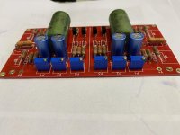
So 6L6 has encouraged me to post photos. So here is how far I have gotten with the FE. Only lacking the MOSFETs with heatsinks. Needed even smaller soldering tips and thinner soldering wire than I had on hand. So awaiting that until doing the last bit.
So this is the first time I solder anyting other than bare wires for fixing things. So it is not perfect, and perhaps not very good. But I believe it is good enough. Takes a bit getting used to choosing the right tips, wire thickness and melting time and such. But slowly getting there. Does not help I am using an almost flux free solder, a favourite of an engineer I know and respect. Only thing is I am not as good a solderer as him. So kinda irritating getting so little help from the flux. On the other hand, joints come out nice and shiny with little or no flux smithered around the board and joints.
So this is the first time I solder anyting other than bare wires for fixing things. So it is not perfect, and perhaps not very good. But I believe it is good enough. Takes a bit getting used to choosing the right tips, wire thickness and melting time and such. But slowly getting there. Does not help I am using an almost flux free solder, a favourite of an engineer I know and respect. Only thing is I am not as good a solderer as him. So kinda irritating getting so little help from the flux. On the other hand, joints come out nice and shiny with little or no flux smithered around the board and joints.
Attachments
But I believe it is good enough. Takes a bit getting used to choosing the right tips, wire thickness and melting time and such. But slowly getting there. Does not help I am using an almost flux free solder, a favourite of an engineer I know and respect. Only thing is I am not as good a solderer as him. So kinda irritating getting so little help from the flux. On the other hand, joints come out nice and shiny with little or no flux smithered around the board and joints.
AFAIK, if you work fluxless, you have to take care that the solder has made a good joint. Glossiness is not per se a good indicator.
I would make sure the parts and the board are definitely clean (use a glass-Tool of which I don’t remember the name and ipa-alcohol). Why not using a separate flux of sorts?
Here‘s a little guide for if it helps:
https://mobile.twitter.com/TechAmazing/status/1316537738120790017
It has 1,2 percent flux, but I am used to much higher ratings, so it acta differently with less «suction» than I am used to. I have a guy that will inspect the joints. Excited, but not too worried. Thanks!
So 6L6 has encouraged me to post photos. So here is how far I have gotten with the FE. Only lacking the MOSFETs with heatsinks. Needed even smaller soldering tips and thinner soldering wire than I had on hand. So awaiting that until doing the last bit.
So this is the first time I solder anyting other than bare wires for fixing things. So it is not perfect, and perhaps not very good. But I believe it is good enough. Takes a bit getting used to choosing the right tips, wire thickness and melting time and such. But slowly getting there. Does not help I am using an almost flux free solder, a favourite of an engineer I know and respect. Only thing is I am not as good a solderer as him. So kinda irritating getting so little help from the flux. On the other hand, joints come out nice and shiny with little or no flux smithered around the board and joints.
When back in stock or for your next project, try the store's fire solder. Otherwise, I've used RadioShack's silver bearing solder since the 90's.
Do perfect your soldering technique, many problems result from poor solder joints. Usually intermittent in nature and difficult to find. Buy a good iron, hopefully that scales up power during use so tip remains same temp in use, and good solder. Kester 44 is easy to find and really good as well.
Put tip so that the pad is heated at same time wire is. Wait until solder melts on the pad, not just wire. When ir flows just bring the tip of the gun up the wire and away. You should have bright shiney little volcano looking solder joints.
Time plays havok with bad joints. Do it right the first time, this amp deserves it.
Russellc
Thanks for the advice! It is actually not always easy to get the island hot enough. But i have checked my joints, and a few have too little, and a few have too much, solder. But no cold joints, hand that is good news. I plan to redo the few with too little or too much solder. You mentioned trouble with DC offset a while back, due to flux mess and such on JFET joints. Can you describe «how bad» it has to be before such issues can occur?
- Home
- Amplifiers
- Pass Labs
- BA-3 Amplifier illustrated build guide