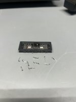
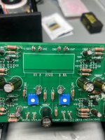
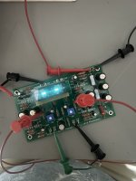
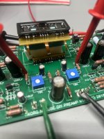
Trully differential no, (quasi) balanced yes. For differential, you must float heater supply. Pete millet made a really nice differential nutube design. But if you intend to add another b1k board, there is a topic here https://www.diyaudio.com/community/threads/balanced-b1-with-korg-triode.341111/
it can
but then why - it will not be neither nice sweetener (loosing that 2nd dominant), nor proper line stage
but then why - it will not be neither nice sweetener (loosing that 2nd dominant), nor proper line stage
Yes, but... why and diy don't go together...
Why is the Mount Everest climbed? Because it's there

But I of course understand what you mean, many thanks for the clarification
Why is the Mount Everest climbed? Because it's there


But I of course understand what you mean, many thanks for the clarification

Many thanks, that's exactly what I was looking for.Trully differential no, (quasi) balanced yes. For differential, you must float heater supply. Pete millet made a really nice differential nutube design. But if you intend to add another b1k board, there is a topic here https://www.diyaudio.com/community/threads/balanced-b1-with-korg-triode.341111/
Hi,
I need some help to set it up.
I have attached picture from measurement, I tried to set the 14V. The pots are almost in center position,
Right channel - T8 test point is 13.51V
Left channel - T7 test point is 15.63V
I used DiAna distorsion analyser, with Cosmos ADC.
Right Channel:

Left Channel:

Now I have exactly the same harmonics (left channel THD is 3dB more (-32.6) compared to the Right channel THD (-35.7) but the shape of the residual amplitude, is the same.
If I try to set the same voltage on both testpoint, then the harmonics looks total different on the left and the right channel, and the potmeters also have different position (one of them 11 hours, the other one is 12 hours)
So guys, what is the more important? Same voltage on T7-T8 testpoint or same harmonics?
I need some help to set it up.
I have attached picture from measurement, I tried to set the 14V. The pots are almost in center position,
Right channel - T8 test point is 13.51V
Left channel - T7 test point is 15.63V
I used DiAna distorsion analyser, with Cosmos ADC.
Right Channel:
Left Channel:
Now I have exactly the same harmonics (left channel THD is 3dB more (-32.6) compared to the Right channel THD (-35.7) but the shape of the residual amplitude, is the same.
If I try to set the same voltage on both testpoint, then the harmonics looks total different on the left and the right channel, and the potmeters also have different position (one of them 11 hours, the other one is 12 hours)
So guys, what is the more important? Same voltage on T7-T8 testpoint or same harmonics?
I will answer your question with some questions:
In each case, how does the distortion change with increasing output level? At maximum output? Is the gain the same for both cases?
I vote for the same voltage at the test point for both channels.
In each case, how does the distortion change with increasing output level? At maximum output? Is the gain the same for both cases?
I vote for the same voltage at the test point for both channels.
I didn’t have the time measure what you asked, just quickly measured the gain.
With asymmetrical TP voltages (same setup as above):
Right channel:961mV RMS
Left channel: 880mV RMS
If I set the left channel TP voltage T7 match with right channel (T8):
Right channel: 962mV RMS
Left channel: 1014mV RMS
With asymmetrical TP voltages (same setup as above):
Right channel:961mV RMS
Left channel: 880mV RMS
If I set the left channel TP voltage T7 match with right channel (T8):
Right channel: 962mV RMS
Left channel: 1014mV RMS
Back to the zero point. I set the T7-T8 voltage to 9.50V output 1V RMS
Voltage drop across 332k
Left 10.80V Right 10.81V
Voltage drop across R1
Left 0.604V Right 0.591V
Voltage on lower leg of 33.2k (near to pot) ref. to GND
Left 3.027 Right 2.485
Voltage drop top leg of the same resistor ref to GND
Left 2.833 Right 2.261
THD
Left 2.13% Right 1.56%
Then I set the THD to same level (1.5%)
T7 test voltage 10.33V t8 test voltage 9.58
H2 null
Left 11.63v THD 0.35% Right 11.1v THD 0.32%
H3 null
Left 7.37V THD 4.31% Right 8.3V THD 2.77%
Then some measurement: T7-T8 set to 9.50 output 1V RMS
Right

Left

Output 2V
Right

Left

Output 3V
Right

Left

Right
Left
Output 2V
Right
Left
Output 3V
Right
Left
Have you any suggestions based on the measurements?I will answer your question with some questions:
In each case, how does the distortion change with increasing output level? At maximum output? Is the gain the same for both cases?
I vote for the same voltage at the test point for both channels.
You did not show any distortion measurements for the case of different T7, T8 voltages and high signal output voltages, especially near maximum output signal voltage.
Results may help you in deciding which way to go.
I
Results may help you in deciding which way to go.
I
Finally. I figured out REW can display the harmonics phase angle.
Now the setup:
T7 voltage 12.56V T8 voltage 12.20V
Left Channel

Right channel

Distorsion vs level Left

Distorsion vs level Right

Summarize, with this setup the two channel's harmonics phase angle are same. The output voltage level is same, but the right channel's distorsion is a bit more.
Now the setup:
T7 voltage 12.56V T8 voltage 12.20V
Left Channel
Right channel
Distorsion vs level Left
Distorsion vs level Right
Summarize, with this setup the two channel's harmonics phase angle are same. The output voltage level is same, but the right channel's distorsion is a bit more.
Still waiting for a high output voltage with a large difference in T7 and T8, since you wanted to decide on whether to choose same T7 and T8 or choose different T7 and T8 that result in similar distortion profile.
I suggest you first test with a 1V output level with voltage at T7 and T8 the same. Then increase the output to 4V.
Next choose a T7 and T8 that result in similar distortion at 1V output level. Then increase the output to 4V with no change to T7 and T8.
Compare the distortion results of all four tests .
Show the 1kHz distortion plots. Use same test setup i.e. all REW or all DiAna, for all four tests for consistency.
Your initial question was whether to choose similar T7 T8 or different T7 and T8 that result in similar distortion at a set output level. That needs to be explored at both low and high output voltage levels to get a complete picture since the preamp will be outputting signals at varying levels depending on the dynamics of the music and the volume level that you choose to listen to the music.
Thanks Ben,
Let me explain a bit more about the usage. I don't want to use it a s a normal premp. It will used in a DAC. I have an AD1865 DAC, and a transformer at the output. The +/-1mA DAC output signal will be converted by a resistor to 150-250mA (it is not decided yet) then I need a stage with high input impedance, low amplification, and low output impedance. Korg B1 looks perfect for this application. But never will operate for example more than 1V RMS since the 0dB line level is around 0.7V RMS.
So what do you think, is the 4V out test still relevant to figure out to what is more important
- same T7 - T8 voltage,
- or same distorsion profile (I mean the same ratio of H2, H3, H4, H5, H6...), and same harmonics phase angle?
The short answer is I would go with equal T7 and T8 voltage.
However, to elaborate, the Nutube in the circuit is wired as a resistor loaded triode voltage amplifier, and its performance is set by its operating point on its loadline. The operating point is the voltage at the anode, T7 and T8 on the B1 Korg pcb, and the quiescent current of the Nutube. That can be set to any point that the designer chooses, and that operating point has an effect on the gain, distortion, and linearity of the circuit.
Changing T7 or T8 changes the operating point.
Since most sound systems are stereophonic, it is best to have both channels of stereo reproduction to be as identical as possible. So in an ideal situation both channels would be set up the same. But due to manufacturing tolerances in parts and equipment, that is not feasible. So some tweaking may be done if desired. But it would be a balance between gain, distortion, and linearity.
You can research tube amplifier operating point and load line on the internet for information. Here is some information:
https://www.analogethos.com/post/load-lines
https://www.vtadiy.com/book/chapter-3-vacuum-tubes-as-amplifiers/3-3-operating-point-and-bias/
As for your intended use of the B1 Korg, perhaps it is not best choice as the distortion of the B1 Korg is quite high. Perhaps the Pass D1 I/V or the Pass Zen IV converter is a better choice.
https://www.passdiy.com/project/other/zen-i-v-converter
There are also threads on diyAudio.
Thank you, I appreciate your help. Then I have to find other gain stage + buffer.
I'm affraid D1 IV, or Zen IV is not applicable, since I have a transformer stage and passive IV after the dac. The only thing what's needed a gain+buffer stage with at least 50-100k input impedance, low gain 5-10x and, low output impedance.
I'm affraid D1 IV, or Zen IV is not applicable, since I have a transformer stage and passive IV after the dac. The only thing what's needed a gain+buffer stage with at least 50-100k input impedance, low gain 5-10x and, low output impedance.
Last edited:
Hi
Having a problem with my B1. It was working fine when last checked. It sat idle on a shelf for a few months. When I plugged it in recently, it started emitting a 5.1k frequency squeal in both channels. I know it isn't the wall wart, as I've tried a different 24v power supply. Being that the problem is on both channels, I suspect a power supply problem on the B1 board.
Can someone offer some troubleshooting help on how to best diagnose my problem, please?

Thank you.
Having a problem with my B1. It was working fine when last checked. It sat idle on a shelf for a few months. When I plugged it in recently, it started emitting a 5.1k frequency squeal in both channels. I know it isn't the wall wart, as I've tried a different 24v power supply. Being that the problem is on both channels, I suspect a power supply problem on the B1 board.
Can someone offer some troubleshooting help on how to best diagnose my problem, please?
Thank you.
Thank you, I appreciate your help. Then I have to find other gain stage + buffer.
I'm affraid D1 IV, or Zen IV is not applicable, since I have a transformer stage and passive IV after the dac. The only thing what's needed a gain+buffer stage with at least 50-100k input impedance, low gain 5-10x and, low output impedance.
Perhaps the DIY Front End 2022 may work for you: https://www.diyaudio.com/community/threads/diy-front-end-2022.394339/
Its gain is adjustable.
- Home
- Amplifiers
- Pass Labs
- B1 with Korg Triode


