Thank you both for responding. The right channel does not have sound. Will look for the article, check resistors and solder. Will report back. Thanks again.
My Balanced Version of the Pass KB1 is now being produced for me by a friend with a familiarity with the KB1.
I have revisited the thread over the past months of Posts and have seen the suggestion that a Battery Power Supply is a worthwhile consideration.
As I have already gone a little of the trail and had Bespoke matched Stepped Attenuators produced for the build, the idea of a the alternative Power Supply has a appeal.
Is it possible to make more known about this method, i.e, does a Power Pack need to be purpose produced or can a 'off the shelf' Power Pack be sourced?
A Balanced KB1 is already in use by the builder of mine, so the Bread Board nearly produced for one channel of my model, can be compared using my VC and the potential inclusion of the Battery Power Supply.
It is a exciting time as I have been demonstrated this Pre-Amp in a variety of Build Guises, and have been impressed with it as a Basic Model and when Modified this Pre-Amp has Wowed me.
Have you tried using a UPS with a large battery to power the B1K? I did, it works fine. I couldn't hear the difference but then I live in suburbia and have 20A homeruns to my stereo, so the AC is clean.
( I guess now we'll need a thread about clean UPS power..)
Are you going to use a battery with a DC output?
Is your B1K fully balanced or did you add the balanced outputs only?
( I guess now we'll need a thread about clean UPS power..)
Are you going to use a battery with a DC output?
Is your B1K fully balanced or did you add the balanced outputs only?
Finished my build today. Everything was straightforward; all test points as described in Nelson's document showed correct values.
First listening test wasn't successful as the preamp has too much gain for the set I connected it to.
I run a Raspberry/Hifiberry DAC HD and a Quad 66 preamp, connected to a Quad 306 poweramp in my office room: replacing the 66 preamp with the NuTube didn't work well, as the signal level to the poweramp was way to high, the signal itself completely saturated, even at the lowest possible level of the NuTube's volume pot.
I guess that's my own fault as the Quad stuff runs on lower signal level. I will put a test bed in place and check the input level vs. the output signal just before clipping. The I need to adjust source output and poweramp input levels to fit the NuTube.
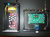
I built a VRDN-based external power supply (designed by Mark Johnson for the DIYAudio forum) for the NuTube, in order to provide it a low noise and stable 24VDC power (stable at least until 1.5A)
The PSU's output is +12V ,0V, and -12V; the connector is grounded, so that the NuTube's case is grounded as well.The NuTube's PCB is isolated from the case. For the NuTube, I only use the +12V and -12V connections of the PSU.
The test point T1 shows 24.1V, and is stable until 1.5 Amps ( I didn't test higher loads).
T5 shows 0.594V, and T6 shows 0.615V.
T7 was adjusted to 9.505V, and T8 to 9.51V.
I will report my findings on the test bed: next listening test maybe with the Q17 poweramp from Tibi Vical from the DIYAudio forum; I don't want change my Quad setup, as it works like a charm.
First listening test wasn't successful as the preamp has too much gain for the set I connected it to.
I run a Raspberry/Hifiberry DAC HD and a Quad 66 preamp, connected to a Quad 306 poweramp in my office room: replacing the 66 preamp with the NuTube didn't work well, as the signal level to the poweramp was way to high, the signal itself completely saturated, even at the lowest possible level of the NuTube's volume pot.
I guess that's my own fault as the Quad stuff runs on lower signal level. I will put a test bed in place and check the input level vs. the output signal just before clipping. The I need to adjust source output and poweramp input levels to fit the NuTube.
I built a VRDN-based external power supply (designed by Mark Johnson for the DIYAudio forum) for the NuTube, in order to provide it a low noise and stable 24VDC power (stable at least until 1.5A)
The PSU's output is +12V ,0V, and -12V; the connector is grounded, so that the NuTube's case is grounded as well.The NuTube's PCB is isolated from the case. For the NuTube, I only use the +12V and -12V connections of the PSU.
The test point T1 shows 24.1V, and is stable until 1.5 Amps ( I didn't test higher loads).
T5 shows 0.594V, and T6 shows 0.615V.
T7 was adjusted to 9.505V, and T8 to 9.51V.
I will report my findings on the test bed: next listening test maybe with the Q17 poweramp from Tibi Vical from the DIYAudio forum; I don't want change my Quad setup, as it works like a charm.
Attachments

Yes, Got the Nelson Pass article..
Test voltages:
T1: 23.9v
T2:23.20v
T3:22.49v
T4:8.65v
T5:0.576v
T6:0.590v
Adjusted the variable resistors to read 10v at T7 and T8 (Had not done this before).
Checked the 33.2K and 332K on board. They measure correctly.
Hooked it back up and had the same result. Right channel is not working. Can you suggest some other checks? Thanks again for your help, Ranga
Last edited:
My inquiry is not as a knowledgeable EE, nearly all the devices I have in use in the system have been built by others for myself, the B1K has the same method being used for the build. I was looking to put the idea on the table, as the Power Supply Option is still Open to discussion.
It is a Fully Balanced Design and will have a option on RCA Phono and XLR.
My Power Amp's are to be converted to Balanced once the Pre-Amp is up and running.
The Pre' is to be compared to another Balanced Design in the possession of the builder, as it is to be slightly different due to some selected components, the intention is to compare the two.
The use of a Battery Power seems fine to myself, especially as the recommendation I picked up on, came within the thread from 'Mark, a very respected contributor, I was thinking it would be a good idea to compare the Battery Powered to the Mains Powered as part of the comparisons.
In the past, I supplied to B1K Builders, the earliest of the mains filters that are produced from Mark's design, these were very well received as a add on part.
Interesting... BTW, I'm not an "EE", that's just my initials..... if my user name were true, it ought to be "Smoke", because I'm good at smoking VERY expensive electronics. But my background is sufficient that I can read most schematics... except for that darn SissySIT.... yikes.
So, if you are fully balanced, will that mean TWO Korgs? I'm really interested on your project since I got a B1K, and F4 and I'm in the process of getting a 2nd F4 and a balanced preamp... plus my A2 and A5 amps also take balanced.
I wonder how hard will it be to get two Korgs to sound the same... do you have to get them "matched" to each other?
Ranga,
The voltages look good so there does not appear to be a problem with the circuit board so far. Another check of the circuit board is to measure the voltage across the two R1 resistors on the bad channel (meter probe on each end of resistor). Also measure the voltage across the good channel R1 resistors for comparison.
If the voltage across the R1 resistors are consistent, then the next thing to check are the input and output wiring of the bad channel. Check for correct wiring and look for bad solder joints at wires to jacks, switches, volume control, etc.
Have you reflowed solder joints? There are dubious ones as noticed in this thread.Yes, Got the Nelson Pass article..
Test voltages:
T1: 23.9v
T2:23.20v
T3:22.49v
T4:8.65v
T5:0.576v
T6:0.590v
Adjusted the variable resistors to read 10v at T7 and T8 (Had not done this before).
Checked the 33.2K and 332K on board. They measure correctly.
Hooked it back up and had the same result. Right channel is not working. Can you suggest some other checks? Thanks again for your help, Ranga
Hi tonyEE
My explanations will be Layman, but should be helpful with your inquiry.
There is a Two Board Balanced Design from recollection covered in this Thread and Pete Millet also has a Balanced Design using the Nutube as well, these Builds are worthwhile seeking out for the ideas that can be gathered.
My EE Friend has a Pass B1K Two Board Balanced Design in use, this evolved after having built a selection of Pass B1K variants, from the earliest being a Basic Build through to where the Builds are at now. Along with these builds others within a Local HiFi Group have adopted this Pre' Design and have a coupe of other variants in use, VC's and Cap's are with differences.
VC's have ranged from cheap Pot's, Pot's with increased expense, TVC, and a range of Stepped Attenuators up to a Khozmo.
As a result of demonstrations, I have become quite confident, as a result of subjective evaluation, that a VC has a noticeable impact on the Sound Produced and the design of the device used, has a discernable sonic when compared.
Cap's also have a discernable sonic when compared, but the influence of the Cap's in use, requires a extended period of listening to detect where the improvements from usage are to be found.
With the above experiences as a guidance and the impressions made from a few other experiences, the intent is for this Pre' to be a end game device, incorporating a few personally selected devices/materials.
I have chosen devices/materials and taken the advice to match components, to keep a close match over the Two Signal Paths, as outlined:
1, Two Bespoke Built Matched Stepped Attenuators are produced.
2, Components are being Matched.
3, Jfets are able to be closely matched using a device that allows for this.
4, Internal Wiring is requested to be a PC Triple C Wire.
5, Chassis Mount RCA - XLR to be Pure Copper and Low Eddy designs.
6, Air Tight Chassis (my choice) and other (EE Friend Selected) measures to control the Ring from the Nutube.
I have been very happy over the past few years to have a loan of this Pre' and regularly be demonstrated them in use in other systems. It is quite exciting the be at the place where I will have my own one ready for the regular usage, when the Home System is reinstated for use.
Ben: Thank you. It is working now and sounds amazing.
I first measured the R1 resistors.
Left Channel:
R1 input side: 0.957v
R1 output side: 0.936v
Right channel (no sound):
R1 input side: 0.924v
R1 output side: 0.967v
Seeing that the readings did not show any clear big difference, I also went over solder on the pcb, removed and re soldered all the connections to the back wall, replaced the input and output wires to and for the Right channel. Hooked it up and still no sound on the right channel.
Since the pcb was measuring similarly on both channels, and I had new wires into the pcb, I next went to the soldering on the Pot. Went over all the connections especially the ones leading to the Right channel and that was it. That did it.
Thank you Ben Mac, Brijac and Dirk for your help. Would not have happened without your help. I am very grateful.
Now between songs I hear a faint sound like a motor. Is that the Nutube being microphonic? I will try the eraser solution that 6L6 had in the build guide which was excellent. Lesson learnt about soldering.
Thanks again to all of you, This is going to be a Sunday filled with music! Ranga🙂
Attachments
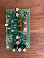
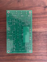
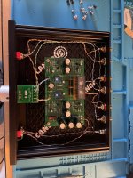
In need of some help to save my build.
Just built a Korg Nutube B1 preamplifier. Hooked it up and it played great! Not bad for my first build, and really cool that Mr. Nelson provides this to us all to build. Then things went sideways.
I swapped another amplifier in to test it before starting a rebuild on the amplifier, it apparently had a bad channel (probably shouldn't have done that). Took that amplifier out, put the other amplifier back in, and after a few minutes of listening I heard a small pop..... then the right channel went pretty much silent. Checked all my connector cables and the music plays fine with the cables with out the Korg Nutube B1 Preamplifier. Hmm... What did I do?
Now, I've read through this thread to figure out how to work through a process of elimination. Read post #1 of this thread for Nelson's article and all the test points for both channels are measuring fine. I hadn't properly adjusted the 10K resistors to get the 10V at T7 and T8. So I adjusted those and both test points are now just below 10V. The Nutube turns on and is glowing blue, appears to still have the filament, and the Left channel sounds great. Read the post about a volume pot problem. Swapped the right channel wires from the volume pot to the left and everything sounds great. Swap the left to the right and the music plays at an extremely low volume and also sounds a bit off.
I then tried resoldering the right output wires and the RCA connectors. Cleaned the bottom of the board and checked all my soldering joints. Still no music from the right channel.
Thoughts? Did I kill the Nutube? Seems to glow and work. What else do I need to check? I've only got a multimeter so no fancy equipment to investigate this with.
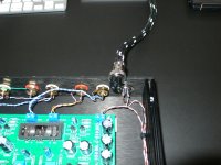
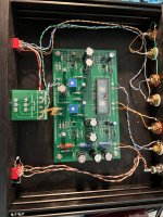
Here are some photos of my Nutube B1. Let me know if you have any thoughts on how to solve this conundrum. Also, thank you for your time, I think my laddy is getting pretty tired of me staring into this black box. Appreciate your guidance.
Just built a Korg Nutube B1 preamplifier. Hooked it up and it played great! Not bad for my first build, and really cool that Mr. Nelson provides this to us all to build. Then things went sideways.
I swapped another amplifier in to test it before starting a rebuild on the amplifier, it apparently had a bad channel (probably shouldn't have done that). Took that amplifier out, put the other amplifier back in, and after a few minutes of listening I heard a small pop..... then the right channel went pretty much silent. Checked all my connector cables and the music plays fine with the cables with out the Korg Nutube B1 Preamplifier. Hmm... What did I do?
Now, I've read through this thread to figure out how to work through a process of elimination. Read post #1 of this thread for Nelson's article and all the test points for both channels are measuring fine. I hadn't properly adjusted the 10K resistors to get the 10V at T7 and T8. So I adjusted those and both test points are now just below 10V. The Nutube turns on and is glowing blue, appears to still have the filament, and the Left channel sounds great. Read the post about a volume pot problem. Swapped the right channel wires from the volume pot to the left and everything sounds great. Swap the left to the right and the music plays at an extremely low volume and also sounds a bit off.
I then tried resoldering the right output wires and the RCA connectors. Cleaned the bottom of the board and checked all my soldering joints. Still no music from the right channel.
Thoughts? Did I kill the Nutube? Seems to glow and work. What else do I need to check? I've only got a multimeter so no fancy equipment to investigate this with.
Here are some photos of my Nutube B1. Let me know if you have any thoughts on how to solve this conundrum. Also, thank you for your time, I think my laddy is getting pretty tired of me staring into this black box. Appreciate your guidance.
Attachments
@RDamodaran glad to have helped. Enjoy the music. As for the motor sound, it could be motorboating, try to resolder psu wires for starters, both to barrel and the pcb.
I am confused - which wires did you swap? Did you connect the volume pot right channel output to the Nutube board left channel input?......... Swapped the right channel wires from the volume pot to the left and everything sounds great. ........
...............
"...everything sounds great..." One channel only or both channels sounds great?
Same question - exactly what wires did you swap, and which Nutube channel had low volume, and what did the other channel sound like?......Swap the left to the right and the music plays at an extremely low volume and also sounds a bit off........
After much thought, it seems to me that you connected the volume pot right channel output to the Nutube board left channel and that worked. Then you connected the volume pot left channel output to the Nutube board right channel and the output was low. I suppose I am a bit slow so it would have helped me if you were more precise in your description. Trouble shooting over the internet is tough as it is.
Since the Nutube voltages measured within specifications, the Nutube is probably ok. But the JFETs may have been damaged.
Please measure the voltage drop across all four R1 resistors.
Last edited:
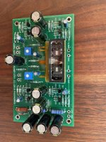
I have build my B1 Nutube. The sound is very good, i used some good Mundorf Silver Gold Oil (0,22uF, 1uF, 3.3uF) from old speaker projects, all cables are Mogami (from 2534 and 2349), star grounding, ps are are 3x 2200 Nichicons, the rest are 1000uF gold Nichicons.
I measured those voltages, tried three different 24V ps.
t1 23,94
t2 23,18
t3 22,4
t4 8,65
t5 0,58
t6 0,6
t7 10,5 - it is minimal possible voltage, i can't go lower
t8 9,25 - it is minimal possible voltage, i can't go lower
My questions:
1. t4 8,6V ? is it OK ?
2. t7 10,5V ? why i can't go lower ?
Now i am listening with t7/8 13.5V and reversed absolute phase at the dac.
Thank you Papa Nelson for this great sounding project 🙂
Last edited:
- Home
- Amplifiers
- Pass Labs
- B1 with Korg Triode