No, no batteries. I am thinking about ~50VA Transformer, schottky rectifier, some nice capacitors and good regulator, at least LM317, but maybe somebody will have a batter idea ?
Hello,
I plan to build a PSU for the B1 based on Mark's VRDN. I want to add the two out pouts to have sufficient voltage. I ordered a 30VA 2x20V trafo; will see if I can tune the outputs to 2x 12V, or if it's better to tune it to 2x13V, in order to keep it cooler.
@mark: any concerns with this approach?
I plan to build a PSU for the B1 based on Mark's VRDN. I want to add the two out pouts to have sufficient voltage. I ordered a 30VA 2x20V trafo; will see if I can tune the outputs to 2x 12V, or if it's better to tune it to 2x13V, in order to keep it cooler.
@mark: any concerns with this approach?
You found a semi ok regulator to call for best possible supply 🙂No, no batteries. I am thinking about ~50VA Transformer, schottky rectifier, some nice capacitors and good regulator, at least LM317, but maybe somebody will have a batter idea ?
Shunt regulated supply is a fine option, some good series regulator like lt1963 is good too. There are many topics on the forum, you can find something you like.
Oh yes, shunt regulator ! But where can i find a good kit now ? So many kits are just sold out ...

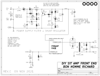
One of the interchangeable Front End cards for the Ship Of Theseus amp, includes a shunt regulator that might be of interest to B1-with-Korg builders. The Front End is called "Bon Homme Richard" and its schematic is attached below.
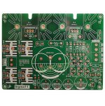
There's an inductor-capacitor lowpass filter at the very input to attenuate high frequency SMPS switching noise (L1+C1 in the schematic; rolloff corner @ 230 Hz), plus a resistor-capacitor lowpass filter for additional attenuation (R1+C1). These are followed by a shunt mode voltage regulator, consisting of a constant current source (M1+Q1) and a constant voltage shunt with error amplifier (Q2+U1). The physical implementation is reasonably small; PCB photo also attached.
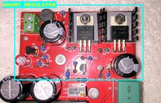
You'd want to reimplement the shunt regulator circuit on its own, smaller, PCB. And get rid of all extra things on Bon Homme Richard (like the Edcor transformer!!) which aren't part of the PSU filter & regulator.
_
There's an inductor-capacitor lowpass filter at the very input to attenuate high frequency SMPS switching noise (L1+C1 in the schematic; rolloff corner @ 230 Hz), plus a resistor-capacitor lowpass filter for additional attenuation (R1+C1). These are followed by a shunt mode voltage regulator, consisting of a constant current source (M1+Q1) and a constant voltage shunt with error amplifier (Q2+U1). The physical implementation is reasonably small; PCB photo also attached.
You'd want to reimplement the shunt regulator circuit on its own, smaller, PCB. And get rid of all extra things on Bon Homme Richard (like the Edcor transformer!!) which aren't part of the PSU filter & regulator.
_
Attachments
Last edited:
I picked this up for my first kit build and all went well except I wired the diode in the power supply back to front and then had to repair the trace after I removed it. Everything tested ok or so I thought, but I have now burned out two nutubes on the channel that you test from T8 (I assume the right channel?). The first I thought was due to a solder bridge but the second was in properly. I've clearly made a mistake somewhere but have no idea where to look or how to test. The filament burnt out each time in a matter of seconds.
The one thing I have found is that I'm getting no voltage across the diode although my diode test is working. As a total noob I have no idea of whether the diode is important to regulating the voltage across the filament or where else to start looking for the problem. My frustration with the whole thing is compounded by the fact that it takes me a month to ship a nutube to NZ. Any help much appreciated.
The one thing I have found is that I'm getting no voltage across the diode although my diode test is working. As a total noob I have no idea of whether the diode is important to regulating the voltage across the filament or where else to start looking for the problem. My frustration with the whole thing is compounded by the fact that it takes me a month to ship a nutube to NZ. Any help much appreciated.
Hi, I use a Chinese clone copy of the Studer 900 24 VDC power supply, driven buy a SMPS. I is unbreakably quite & stable. Easily good enough for a Phono amp let alone a Pre. Had mine in service for over two years now, with no prob's.
Many users upgrade some of the components in the supplied one, but that is now normal for Chinese supplied components.
https://www.ebay.com/itm/1955187410...ykhY0kJ8VHFIhoh8s7Tc+tL3C2E=|tkp:BFBM8NPb-tph
Cheers
Many users upgrade some of the components in the supplied one, but that is now normal for Chinese supplied components.
https://www.ebay.com/itm/1955187410...ykhY0kJ8VHFIhoh8s7Tc+tL3C2E=|tkp:BFBM8NPb-tph
Cheers
NZRob, The 9.1V zener diode definitely regulates the filament voltage. Without it, 24V instead of 9V is sent to the filament. So you need to have a working diode properly installed (stripe in same direction as symbol on pcb).
Please post well lit and focused pictures of the front and back of the board. Also include pictures of the overall build, showing wiring, input jacks, and switches, etc.
Check that the 475 Ohm resistors (located next to T5 and T6) are the correct value. They are part of the filament circuit. Also check the 33.2K and 332K resistors to make sure that they are installed in their proper locations. People have mixed them up.
I'm guessing that my trace repair didn't work - is there any reason that only one filament would blow if the voltage were that high? I've previously checked the 33.2 and 332 resistors and they were all fine just checked T6 and it's showing fine at 474 but T5 is coming in at 212ohm.
I've attached a picture of the board from the top and bottom. I have just realised as I uploaded this that I somehow missed soldering the pins on the daughter board for the bust channel. I'm gonna guess that's my problem right there.


I've attached a picture of the board from the top and bottom. I have just realised as I uploaded this that I somehow missed soldering the pins on the daughter board for the bust channel. I'm gonna guess that's my problem right there.
If the right channel 475 Ohm resistor measured 212 Ohm, that is not good. Desolder and lift one leg and measure and confirm the value. Replace it if it does not measure 475 Ohm or close to it. Perhaps it was damaged when the diode was reversed. A resistance of 212 Ohm would increase the current and voltage to the filament, which could damage it.
As for the voltage across the zener diode, you should get 9VDC if it is working properly. If the diode is blown, it would measure the full power supply voltage of 24V. If you measure 0V, then there is a continuity issue. One or both ends of the diode is not connected to the board.
This filament power/voltage issue needs to be resolved before installing a new Nutube.
If the Nutube right channel is not soldered to the board, keep it disconnected until the filament power issue is resolved. Perhaps the may have saved your Nutube. Also disconnect the Nutube left channel until the zener diode issue is resolved.
Last edited:
I fixed the solder for the daughter board (the korg is a bust - you can see the filament has broken), I fixed the trace for the diode and am now getting 9.5v across it. I removed the t5 resistor and it tested perfectly but when I put it back on it went back to 212ohm - it's in the channel that didn't burn out either time though. In fact it's still working and can be set to 10V with the trim pot (see pic). I suspect that the diode trace failing and some arcing on the loose legs of the korg has been my problem. I now have to wait a month for the next valve to ship so I can find out...

Bad zener diode connection puts 24V in the filament circuit, so that contributed to the toasted filament. 🙁
Thanks for your advice on this, Ben. After the second tube burned out I was just about ready to pack the project in.
- Home
- Amplifiers
- Pass Labs
- B1 with Korg Triode