Hi everybody.
My B1 Korg is in daily use at home and bringing much joy - dialed in at around 9.5V on T7 and T8 with phase inversion corrected at the speaker terminals.
I'm using the recommended Meanwell SMPS but it's started humming so I'm looking to replace with either a fairly generic R-core based Chinese 24V linear power supply or... something else.
What are folks here using? To save me trawling through >500 pages can anyone please recommend a DIY power supply build suitable for a newb-ish?
TIA, Haden
I've bought ready made filter/rectifier boards from e-bay and had one very expensive one spare. So I paired it up with Galaxy 2U case with Aluminium lids. You can use a router and circle jig to cut neat holes in the lid and poke a fully shielded Toroidy transformer through the top.

Toroidy transformer and Salas BiB Salas SSLV1.3 UltraBiB shunt regulator
Would a 22 volt 25VA transformer be sufficient for the UltraBiB and B1-K?
The build guide have good recommendations. Guide says from 50VA.
I used a 50VA with 23V secondary.
https://www.diyaudio.com/forums/att...shunt-regulator-ultrabib_build_guide_0v0b-pdf
I used a 50VA with 23V secondary.
https://www.diyaudio.com/forums/att...shunt-regulator-ultrabib_build_guide_0v0b-pdf
What!! Korg uses tiny amps though- The ultralinear power supply board I bought takes in 24 volt AC from the transformer and outputs 24vdc that's a little different to the norm where boards step up the volts a bit.
I'm running 230volt primary with two 24volt secondaries and just 20VA. I thought that was a bit over the top.
The transformer runs stone cold compared to the 300VA ones I use for each of my ACA.
I'm running 230volt primary with two 24volt secondaries and just 20VA. I thought that was a bit over the top.
The transformer runs stone cold compared to the 300VA ones I use for each of my ACA.
The B1K recommended parts list SMPS supply is 24VDC @ 500mA = 12 watts. And that's probably conservative.
What!!
🙂 Sensible reaction! Korg at 60mA and Ultra BIB ~200-300mA for margins.
AMB sigmas 11 and 22 for all of my gear. Improvements from modest to quite noticeably better.
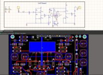
i'm designing my own PCB, but i've faced connecting of filaments (f1's, f2, f3's) to be unclear for me. Could someone please explain whether f1's are both connected to 475 ohms and 1000 uF as well as f3's? And what about f2? Is it connected directly to the ground?
Attachments
Last edited:
i'm designing my own PCB, but i've faced connecting of filaments (f1's, f2, f3's) to be unclear for me. Could someone please explain whether f1's are both connected to 475 ohms and 1000 uF as well as f3's? And what about f2? Is it connected directly to the ground?
Narside:
B1K design: F1 has a 1000ufd capacitor to ground and a series 475 ohm resistor connected to the filament power supply 'H'. F3 duplicates those components and connections. F2 is connected to power supply ground.
Although component values are different, I have included the Pete Millett buffer schematic which makes these connections more clear.
Attachments
Thx
Thanks to everyone that responded. I'll have a look at both UltraBiB and Amb Sigma.
Amb Sigma 11/22... Good bass great staging/focus. And not hot
AMB sigmas 11 and 22 for all of my gear. Improvements from modest to quite noticeably better.
Thanks to everyone that responded. I'll have a look at both UltraBiB and Amb Sigma.
i'm designing my own PCB, but i've faced connecting of filaments (f1's, f2, f3's) to be unclear for me. Could someone please explain whether f1's are both connected to 475 ohms and 1000 uF as well as f3's? And what about f2? Is it connected directly to the ground?
Narside:
B1K design: F1 has a 1000ufd capacitor to ground and a series 475 ohm resistor connected to the filament power supply 'H'. F3 duplicates those components and connections. F2 is connected to power supply ground.
Although component values are different, I have included the Pete Millett buffer schematic which makes these connections more clear.
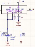
So it looks like that F1 nets should be connected the way shown on the picture (the net is highlighted. Please do not consider the 33.2R resistor due to it's for simulation only).
Attachments
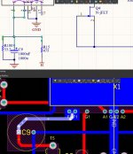
Filament connections:
F1 = pins 1/2 channel 1 V+
F2 = pins 8/9 common (ground)
F3 = pins 16/17 channel 2 V+
Your net connections for channel 1 look correct. Channel 2 is not shown. Schematic looks wrong, ground does not connect to pin 16.
F1 = pins 1/2 channel 1 V+
F2 = pins 8/9 common (ground)
F3 = pins 16/17 channel 2 V+
Your net connections for channel 1 look correct. Channel 2 is not shown. Schematic looks wrong, ground does not connect to pin 16.
Should the jFets be matched by quads? Or all 8 parts should be within +-0.1 mA(or 4-8 as stated in the article). And one more question- is it ok to use the power supply from my aleph j (traditional design as in the build guide) or to use something like sigma 22. I wanted to place the preamp in the same case as my amp.
Last edited:
If you have a distortion analyzer with which to calibrate the tube's bias, then
matching is unnecessary and the current source resistor would be set to any
value that gave a convenient bias current - probably something a bit lower than
the follower's Idss.
If you have but a voltmeter and my approximate calibration graph, then you would
want to have the follower run at Idss so as to conveniently measure the Plate
voltage of the tube - the impedance of the Plate is very high, and your typical
multimeter will load it down, but if the follower is at Idss then the voltage at the
Source pin will equal the Gate voltage, which is also the Plate voltage.
If you have matched fets top and bottom, and a reasonably low Idss (<10 mA)
then you just run 0 ohms for the Source resistor on the current source and you're
all set....
Extra Grounding Needed?
My 3D-printed case is non-conductive. Should I add ground connections from the mounting holes to something? Any other ground connections needed?
Thanks,
Richard.
My 3D-printed case is non-conductive. Should I add ground connections from the mounting holes to something? Any other ground connections needed?
Thanks,
Richard.
- Home
- Amplifiers
- Pass Labs
- B1 with Korg Triode