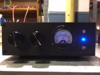
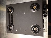
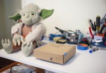
I finished my B1 Korg Triode preamp today, I had a four position select switch in stock, so 4 inputs. ALPS volume control, and a 0 -15v meter on the front panel for T7 - T8 selected by the upper toggle switch. Shouldn't tube amps have a voltmeter?
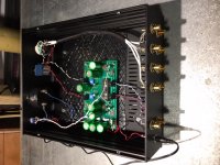
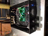
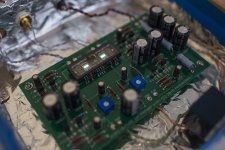
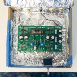
I used 3M automotive sound deadening for the upper and lower panel, memory foam under the tube, Vibrapods for feet, and 3mm rubber mounts for the PCB,
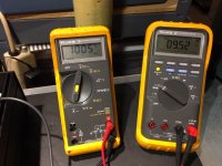
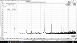
With 1 v output, using Behringer UM2, Akitika 1K generator and REW software:
9.5vdc on T7/T8 = 1.28% H2
10.25 vdc = 1% H2
11.56 vdc = 0% H2 (null point)
11.97 vdc = 0.58% H2
12.4 vdc = 1% H2
I used 3M automotive sound deadening for the upper and lower panel, memory foam under the tube, Vibrapods for feet, and 3mm rubber mounts for the PCB,
With 1 v output, using Behringer UM2, Akitika 1K generator and REW software:
9.5vdc on T7/T8 = 1.28% H2
10.25 vdc = 1% H2
11.56 vdc = 0% H2 (null point)
11.97 vdc = 0.58% H2
12.4 vdc = 1% H2
Attachments

I finished my B1 Korg Triode preamp today, I had a four position select switch in stock, so 4 inputs. ALPS volume control, and a 0 -15v meter on the front panel for T7 - T8 selected by the upper toggle switch. Shouldn't tube amps have a voltmeter?
I used 3M automotive sound deadening for the upper and lower panel, memory foam under the tube, Vibrapods for feet, and 3mm rubber mounts for the PCB,
With 1 v output, using Behringer UM2, Akitika 1K generator and REW software:
9.5vdc on T7/T8 = 1.28% H2
10.25 vdc = 1% H2
11.56 vdc = 0% H2 (null point)
11.97 vdc = 0.58% H2
12.4 vdc = 1% H2
WOW beautiful build!!! I love the Voltmeter!
Now you just need to change signal caps to have maximum out of it 😉
Pass DIY Addict
Joined 2000
Paid Member
Nice work, especially with all of the dampening! I like the switchable volt meter for easy reading/adjustment!
Hi Vunce
Glad you enjoyed the report and it has been of some use!
Enjoy Papa's B1 Korg very much
Claude
Glad you enjoyed the report and it has been of some use!
Enjoy Papa's B1 Korg very much
Claude
Nice built Elwood625, and nice measurements! Thanks for sharing all these details
As you went already for upgraded PS caps, indeed the ones in the signal path could (should?) be next on the list for such a nice built as yours... the Blue Alps potentialy also...
Long live the B1 Korg!
Claude
As you went already for upgraded PS caps, indeed the ones in the signal path could (should?) be next on the list for such a nice built as yours... the Blue Alps potentialy also...
Long live the B1 Korg!
Claude
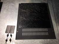
CI also picked up a set of these rubber shock absorber mounts for under the Korg board to see if they help better insulate the Korg tube from vibration: M3 Rubber Shock Absorber Damping Anti-Vibration Holder for F3 F4 Kiss FC M2Y5 | eBay
Because mount all of my boards with M3 hardware, it's a simple swap for rubber mounts. I'll do both changes at the same time when things arrive next week.
Digi-Key offers similar 3M vibration dampers:
MF-100-UC04-H 3M - Aearo Technologies, LLC | Hardware, Fasteners, Accessories | DigiKey
I purchased both 4-40 and 6-32 versions, but they seemed too stiff to really make much difference. Still worth playing with to improve vibration control.
Hi folks,
The Korg B1 was my first-ever DIY audio project, built with the board & JFET kit in the store. I really appreciate all the information and build photos folks have shared in this thread and of course want to thank Nelson Pass for the design and all his contributions and hard work in the DIY space.
I also want to shout out Fabian85 for inspiring me in my choice of chassis.
I used this Mouser BoM to source the components (I'm just using the Meanwell wall wart for now) with the exception of substituting a 1.3W BZX85B9V1-TAP Zener based on previous discussions in this thread.
I used twisted-pair CAT-6 for the signal wiring and attached the NuTube to the board with the double-stick stuff included in the NuTube box. I will probably add some hot glue down the road to reduce the microphonics even further.
I tried it as a preamp for my Harmon Kardon HK3490 receiver and for the ACA 1.6. I haven't yet plugged it into a sound card to measure the distortion but it sounds good to my ears at the recommended 9.4-9.5V range on the two pots with the speaker polarities reversed at the amp. I also tried it at 11.5V range (nulled 2nd-harmonic) and have to confess I am unable to detect much of a difference. Need to spend some more time listening.
I also used furniture pads to create little feet at the bottom of my Premium Chassis.
In the future, now that I know I enjoy listening to it, I plan to relocate it to a remote-controlled passive preamp enclosure from Ebay.
I made one mistake with the wiring of the input channels and had to updated the documentation (photo below).
I had a lot of fun with this build - so much so that I built an ACA to go with it and am in the process of collecting the parts for an F6 build for my main system.
Attachments

Pass DIY Addict
Joined 2000
Paid Member
I purchased both 4-40 and 6-32 versions, but they seemed too stiff to really make much difference.
I have no idea what types of standards or measurements exist in this domain - it seems to me that softer is better, but I don't know what to look for in terms of specs...
Pass DIY Addict
Joined 2000
Paid Member
The Korg B1 was my first-ever DIY audio project, built with the board & JFET kit in the store.
Congrats on a successful first build! My first build blew up on first power up because of a wiring error. It won't be long before you have a second build, a third build, ... a twentieth build... 😀. Welcome to the DIY club!
The Korg B1 was my first-ever DIY audio project, ...
I had a lot of fun with this build ...
metaphile, congratulations!
Looking good 🙂
Regards, Claas
Hi folks,
I also used furniture pads to create little feet at the bottom of my Premium Chassis.
I had a lot of fun with this build - so much so that I built an ACA to go with it and am in the process of collecting the parts for an F6 build for my main system.
Heh, Heh! Premium cardboard chassis are hard to source!
Here are the graphs from REW for distortion measurements:
Left channel @ 11.52 vdc (null)
Right channel @11.41 vdc (null)
Right channel @ 9.5 vdc 1.58% 2H
I made two big errors which I've corrected, why did I think that all the input grounds could be tied together? That does not work, also the RCA chassis connectors I bought from an Amazon partner were junk, the red were to large a diameter for interconnects to fit and the black were to small for interconnects.
All of that has been removed/replaced, now everything works like it should. (With all the grounds together, the volume control had no effect and all the other selected inputs had half volume no matter what.)
I keep learning!
Attachments


Hmmm... don't want to sound harsh so please forgive me for the silly questions and odd post...
Just trying to learn... having a real Fourrier analyzer is very tempting for our hobby but the only tools I know of (my knowledge is indeed limited) that provides this with real data (so no DSO 068 etc. that provide just "some results and figures" indeed) are very expensive oscilloscopes...
I don't know REW so can't judge, it is just the second time I try to understand figures posted obtained through that tempting tool I read here about in another post. But it looks now to me like a tool that provides a lot of numbers and figures after the comma (read high precision level)... without garanteed consistency. Reminds me of multimeters with 3 digits after the comma on the display ... and 5% accuracy in the specs. Ahem...
I understand the figures are with a signal at nearly -20dB - that's Ok. I can't though help wondering as a non REW expert about what seems to me as inconsistencies in the channel results where it matters the most. For example, PS noise seems to come and go in level and harmonics and also the harmonic profile that seems to differ quite a bit through measurements.. or is that last one though channels only? At that level I start personaly wondering about the measurement process (we are mere mortals...) and even possibly the tool rather than the raw results...
Just me? Admittely trying to measure what is (really) happening at -130dB requires quite a bit of care and some harware...
Just thinking loud, thanks again for sharing these data and graphs that have the merit to trigger some thoughts, without I am sure detracting you from what is for sure in real life an excellent sound! And possibly real similar or different measurements, who knows!
For the analysis to be meaningful, the output signal level needs to be known, so that it can be compared to others. A common level for preamp distortion analysis and comparison is 1V rms.
The B1 Korg was measured at 1 v rms as per Nelson Pass where he describes the adjustment. The M2x was measured at 2 v rms into 4 ohms.
Both the amplifier and preamp were warmed up for 1 hour playing great music before any measurements were taken.
Both the amplifier and preamp were warmed up for 1 hour playing great music before any measurements were taken.
I had a lot of fun with this build - so much so that I built an ACA to go with it and am in the process of collecting the parts for an F6 build for my main system.
I'm using an F6 with my B1 Korg for mid/high amplification in my main system. The combination is wonderful.
I made two big errors which I've corrected, why did I think that all the input grounds could be tied together? That does not work... All of that has been removed/replaced, now everything works like it should. (With all the grounds together, the volume control had no effect and all the other selected inputs had half volume no matter what.)
I keep learning!
Shared grounds on the inputs is how I was planning on wiring mine. Is that always the case that it won't work?
- Home
- Amplifiers
- Pass Labs
- B1 with Korg Triode