Pass DIY Addict
Joined 2000
Paid Member
Enochrome: I would recommend a few things:
1) Double check ALL parts - make sure correct value parts are in the correct locations.
2) Since you said you had trouble soldering, it might be worth reflowing each of your solder joints. Let your iron warm up, touch each solder joint again to remelt it, then let it cool.
3) When you have reflowed all of the solder joints, check each one with a magnifier under a bright light. Make sure you don't have any inadvertant solder bridges where they shouldn't be. When solder pads are close together, take a fine blade screwdriver and scratch between the pads to make sure there is no solder where it shouldn't be.
4) If things don't improve after this, follow 6L6's advice: post well-lit, in-focus, decent-resolution images so we can see what is going on.
..so I replaced it with chunk of cedar left over from a closet project.
Love the figuring on the faceplate. Really nice build there Eric!
Pass DIY Addict
Joined 2000
Paid Member
Thanks! It turned out better than I thought. I had saved a few pieces years ago. After some time laying around, all of the purples had turned generic brown. Some sanding revealed the color again, so I guess it oxidized. I put a few coats of shellac on top, so maybe the color will last a little longer this time around.
Hello,
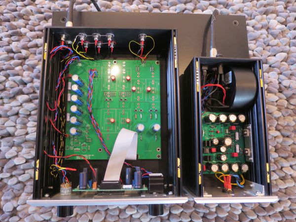
here is my finished Korg 🙂
[url=http://abload.de/image.php?img=korg2nd09gqjy0.jpg] [/URL]
I got the PCB of a friend. It has a separate PCB for the Nutube, a lot of space for Caps (I took small Black Gates 😉), two PSU connectors (wall wart or S11) and the option for a Mute switch (I don´t need it).
[url=http://abload.de/image.php?img=korg2nd05fij7a.jpg] [/URL]
The S11 PSU has two output voltages. A 24V and a 9V which supplies directly the Nutube.
I took a 50K TKD volume pot which works very fine.
[url=http://abload.de/image.php?img=korg2nd156gjcq.jpg] [/URL]
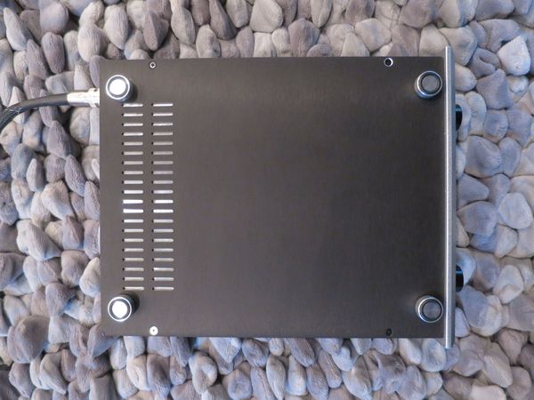
I dont´t like screws in the bottom so I always install a second bottom plate for fixing the PCB and other screws etc. .
This second plate is mounted with the feets 🙂
[url=http://abload.de/image.php?img=korg2nd195zj3b.jpg] [/URL]
Thank you Mr.Pass for this very well sounding Pre-Amp!!!
Kind regards
Andreas
here is my finished Korg 🙂
[url=http://abload.de/image.php?img=korg2nd09gqjy0.jpg]
 [/URL]
I got the PCB of a friend. It has a separate PCB for the Nutube, a lot of space for Caps (I took small Black Gates 😉), two PSU connectors (wall wart or S11) and the option for a Mute switch (I don´t need it).
[url=http://abload.de/image.php?img=korg2nd05fij7a.jpg]
 [/URL]
The S11 PSU has two output voltages. A 24V and a 9V which supplies directly the Nutube.
I took a 50K TKD volume pot which works very fine.
[url=http://abload.de/image.php?img=korg2nd156gjcq.jpg]
 [/URL]
I dont´t like screws in the bottom so I always install a second bottom plate for fixing the PCB and other screws etc. .
This second plate is mounted with the feets 🙂
[url=http://abload.de/image.php?img=korg2nd195zj3b.jpg]
 [/URL]
Thank you Mr.Pass for this very well sounding Pre-Amp!!!
Kind regards
Andreas
this really deserves separate vertical plate (between side panels) , placed near input RCAs , selector switch and pot mounted on , and extending shafts to front plate
I know but unfortunately I don´t like extended shafts.
For the Korg I can live with a few centimeter of silver plated teflon wire 😀
For the Korg I can live with a few centimeter of silver plated teflon wire 😀
Pass DIY Addict
Joined 2000
Paid Member
I was not sure where to post this question,
but I have a Millet NuTube buffer board and when completed and hooked
up to a 12v 5ah battery I get a loud buzzing sound. Could this be a ground
issue?
Possibly related - I recall that Pete Millet has posted that there have been
instances of oscillation in the bipolar followers, and so recommends a
base stopper resistor. I don't recall the value, but 1K would be safe.

Enochrome:
I have built both the Nutube Buffer and the Nuhybrid headphone amp with the recommended 1K base stopper resistors and have had no problems. Both of mine are using a 24v supply, not 12v.
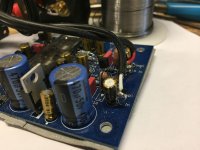
I've attached a photo of how I stuck one leg of the input cap (changed to a 10 ufd electrolytic) into the + input pad, air wired the input to the free leg and commandeered the input cap pads to insert the 1K resistor mounted vertically.
I also replaced Pete's recommended 475K plate resistors with Papa's recommended 332K resistors and used Papa's recommended 9.5V plate voltage settings. I think that both devices sound much better for the changes. For the headphone amp, I also changed the power supply input buffer voltage divider resistors from Pete's 475K to Papa's B1 Korg circuit values of 332K, although I'm not sure that matters.
In comparing the Nutube Buffer (Mosfet inputs) to the Headphone Amp (Bipolar inputs) to the Korg B1 (Jfet inputs) the Nutube pretty much dominates to the sound. Once everything gets 332K plate resistors and a similar 2nd harmonic level, they all sound pretty close to each other. Papa's B1 Korg does win the shootout for being quieter and smoother sounding while perhaps a bit more open at the same time. Probably a combination of better power supply and the Jfet buffers.
All of these circuits invert the input polarity, which happens at the Nutube. Some listening to the headphone amp with the inputs reversed by some isolation transformers has convinced me that proper phase at the transducers is critical. Easy to do with loudspeakers but the headphones required the transformers due to their common ground connection.
My next step is to A-B the $6 Triad TY-250P input transformer against some $75 Jensen JT-11-P-1 transformers. No doubt the Jensens will win but I am curious to see how close the Triads get.
Attachments
Please post your findings regarding the Triad here, that could be an interesting solution indeed for headphones 🙂
Claude
Claude
Hello,
here is my finished Korg 🙂
[url=http://abload.de/image.php?img=korg2nd09gqjy0.jpg][/URL]
I got the PCB of a friend. It has a separate PCB for the Nutube, a lot of space for Caps (I took small Black Gates 😉), two PSU connectors (wall wart or S11) and the option for a Mute switch (I don´t need it).
[url=http://abload.de/image.php?img=korg2nd05fij7a.jpg][/URL]
The S11 PSU has two output voltages. A 24V and a 9V which supplies directly the Nutube.
I took a 50K TKD volume pot which works very fine.
[url=http://abload.de/image.php?img=korg2nd156gjcq.jpg][/URL]
I dont´t like screws in the bottom so I always install a second bottom plate for fixing the PCB and other screws etc. .
This second plate is mounted with the feets 🙂
[url=http://abload.de/image.php?img=korg2nd195zj3b.jpg][/URL]
Thank you Mr.Pass for this very well sounding Pre-Amp!!!
Kind regards
Andreas
Wow! Sehr schick Andreas...😉
Please post your findings regarding the Triad here, that could be an interesting solution indeed for headphones 🙂
Claude
+1 definitely interested to hear your results.
Can anybody point me in the right direction as to what I should look for when selecting an audio transformer to couple with 32ohm headphones?
Thanks Zen. I can use with just a jumper soldered in place; no resistor needed?
Last edited:
correction previous post
Correction:
I only added gate stoppers to the Nutube Buffer since it has Mosfet inputs. My headphone circuit is running the stock bipolars without base stoppers and no oscillation.
The bipolar inputs still have the recommended 100nF Wima film caps. I suppose this value can be so low due to the very high input impedance of the bipolar base.
On the Mosfets, I upped the caps from the 100 nF to 10 ufd electrolytics since that seemed prudent for full frequency response with the newly added 1K gate stoppers.
Enochrome:
I have built both the Nutube Buffer and the Nuhybrid headphone amp with the recommended 1K base stopper resistors ...
Correction:
I only added gate stoppers to the Nutube Buffer since it has Mosfet inputs. My headphone circuit is running the stock bipolars without base stoppers and no oscillation.
The bipolar inputs still have the recommended 100nF Wima film caps. I suppose this value can be so low due to the very high input impedance of the bipolar base.
On the Mosfets, I upped the caps from the 100 nF to 10 ufd electrolytics since that seemed prudent for full frequency response with the newly added 1K gate stoppers.
clarify - what jumper , what resistor?
R1 on the circuit board for use when using J113 or a jumper when using K170. I was unsure whether a resistor was needed depending on the idss.
Yes. The value depends on the Idss of Q1 and Q2. Ideally we want the current
through Q1 to be about 10% or so less than its Idss in the range from about 6 to
9 mA. The Idss of Q2 and R1 are used to set the current of Q2 to that figure.
through Q1 to be about 10% or so less than its Idss in the range from about 6 to
9 mA. The Idss of Q2 and R1 are used to set the current of Q2 to that figure.
- Home
- Amplifiers
- Pass Labs
- B1 with Korg Triode
