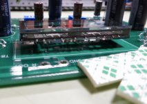
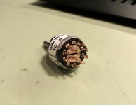
A couple of pieces of two-sided foam tape under the NuTube is helpful.
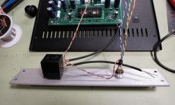
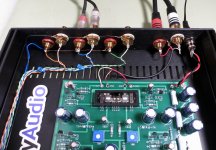
This switch is very nice, but quite small. The inputs will be taken to the outer ring of terminals, the output is the center pins.
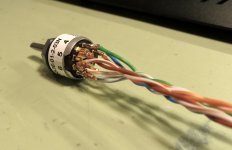
To give you an idea of the size, the wire used is the twisted pair from inside a CAT-5 networking cable. (One of my very favorite sources for good signal wire.) The copper conductors needed to be smushed and shaped a bit to fit inside the solder holes.
Attachments
Last edited:
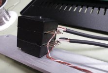
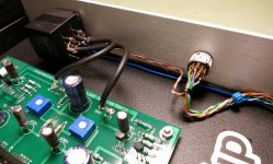
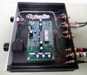
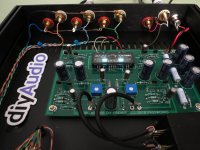
Chassis wiring
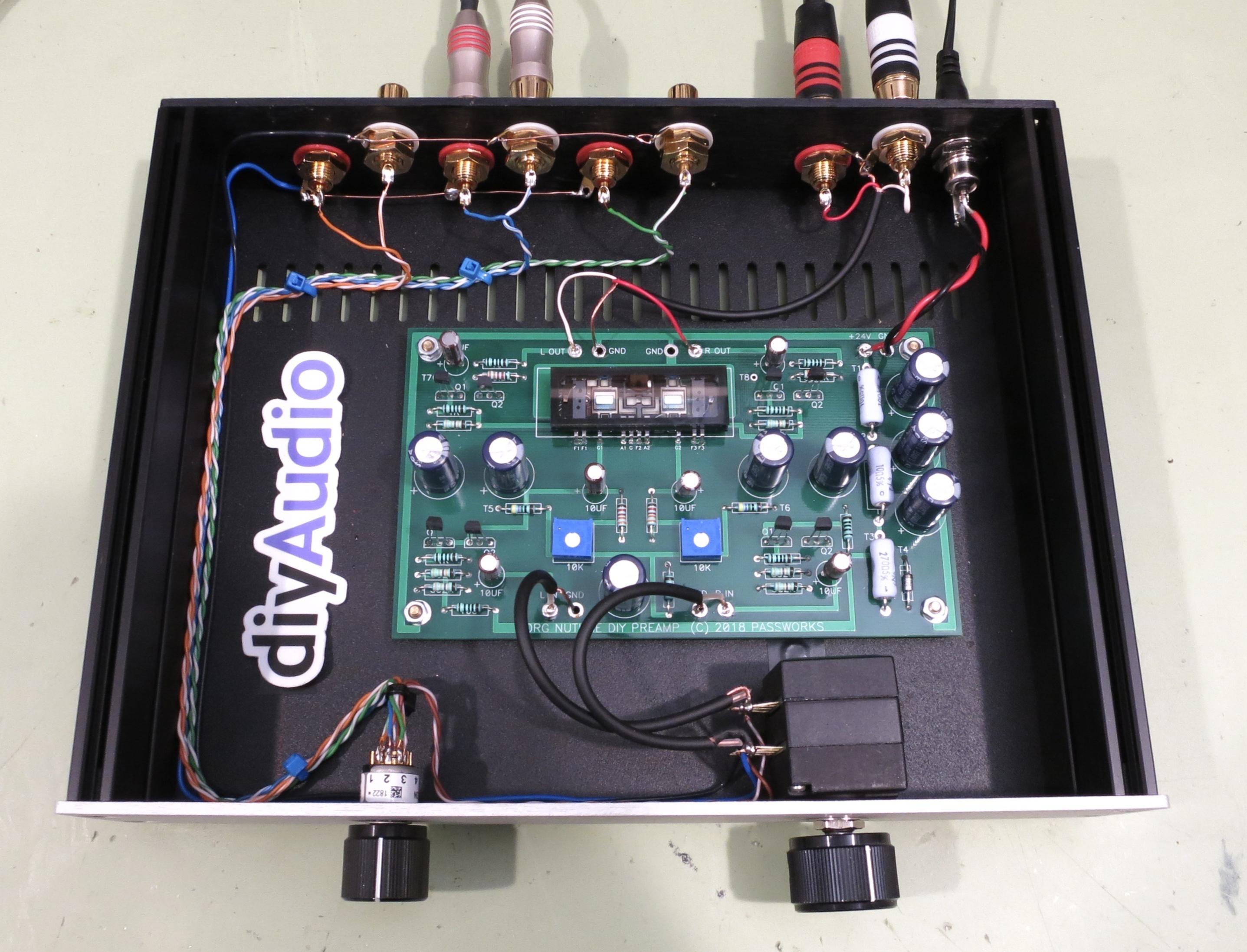

Yes, I used a lot of different types of wires. I wanted to try a few different things as I just received a few of the various cables. It could easily and quietly all be wired with the Cat-5 wire if you like. Use what you have on hand.
Please note that I wired my outputs IN phase. Nelson's article and the video mention that you might want to wire them out of phase for max effect, but you can of course do that at your speaker wires quite easily as well. It's up to you how you want to do it.
Attachments
Last edited:
Will there be a board + resistors/JFET option w/o chassis for people who already have some of the pieces?
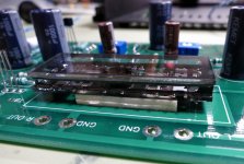
The board is cute as a bug in a rug.
Silicon gel under the board (or the chassis) for vibration isolation, get one of these and cut it to form:
1X Silicone Gel Surgical Suture Exercises Practice Skin Model Non-toxic Hospital | eBay
The board is cute as a bug in a rug.
Silicon gel under the board (or the chassis) for vibration isolation, get one of these and cut it to form:
1X Silicone Gel Surgical Suture Exercises Practice Skin Model Non-toxic Hospital | eBay
Will there be a board + resistors/JFET option w/o chassis for people who already have some of the pieces?
Most likely. 😀


Thnx.Nominally I’d suggest placing the transformer away from the potentiometer. 🙂
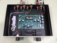
There are a few ways to jigger the positioning, including putting the power supply outboard. That's to be determined. Maybe the power supply on/off with the hole on the right with the Korg board on the left and the volume and 10k potentiometers on the left.
I am a rank beginner, so I am sure things will get worse before they get better.

Nominally I’d suggest placing the transformer away from the potentiometer. 🙂
Is this a better arrangement?
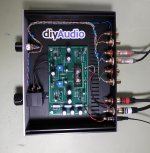
The above photos conform to this schematic; the XMAS version --
You say build conforms to xmas schematic but:
1) It appears you used the 1K gate stopper resistor between the Korg plate and the output JFET, as found on the PCB. If following the schematic, would it not be be a jumper instead?
2) It's hard to read the band colors in the photo for the post-output cap resistors. Are they the PCB values or the schematic values?
I have read in previous posts that the above choices are optional. Just wondering if there are recommendations one way or the other. Seems like the 1K plate to gate would make things more stable but possibly change the sound a bit. The 100/33.2K vs 221/332K choice seems less significant although 100/33.2K again seems a more stable choice.
Hi all,
many thanks to qwertyl ans all other that involved, specially Mr Pass, THANKS!
I'm so lucky to get one of them because I was on the waiting list.
many thanks to qwertyl ans all other that involved, specially Mr Pass, THANKS!
An externally hosted image should be here but it was not working when we last tested it.
I'm so lucky to get one of them because I was on the waiting list.

Yep, doing the little leg dance ... 😀
I'm chicken, though, always using shrink tubing on one of the legs ... 😛
Best regards,
Claas
I'm chicken, though, always using shrink tubing on one of the legs ... 😛
Best regards,
Claas
Question from a "kit" builder: Two PCB's would make a balanced version?
I asked before:
O.K.
Here it is an other question.
As you probably know, I'm a Wacky man, with my balanced mania.
I will intend to use two B1 Korg Boards balanced.
What will be then with second harmonics?
If understand well, in this case second harmonics will extinguish each other.
It will kill its charming soundscape.
Any thoughts?
It is for sure, I think.
But what will be happen to second harmonics?

- Home
- Amplifiers
- Pass Labs
- B1 with Korg Triode