


...so I'm considering using a single dual-gang pot to adjust bias without dissasembling the unit and perhaps even set it differently depending on what music I'm listening to... Are there any reasons (sonic? or other) to avoid a single pot or perhaps to do this even with separate pots?
That is a really cool idea that I saw somewhere along this line of thinking. I forgot about it. might want to have some test points easily accessible too on the rear of the unit.
Hello Ixnay,
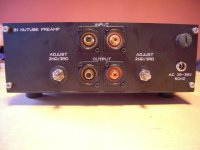
I did this with my B1K-NUTUBE-preamp and with my H2-generator. Multiturnpots accessable from outside and testpoints outside.
Pics in my post #7880 in this thread.
Cheers
Dirk
I did this with my B1K-NUTUBE-preamp and with my H2-generator. Multiturnpots accessable from outside and testpoints outside.
Pics in my post #7880 in this thread.
Cheers
Dirk

Good idea.
I suggest keeping the original pots to define a matched central value and lesser pots to trim both sides in unison.
Once you get the bias voltage centered you will find that relatively small variations will give the effect range you are likely to want.
I suggest keeping the original pots to define a matched central value and lesser pots to trim both sides in unison.
Once you get the bias voltage centered you will find that relatively small variations will give the effect range you are likely to want.
No, that's fine. When you said "post Gerbers" and "flex" I assumed that you have a flex with stiffener. If you are using wires, no problem - sorry, I stand corrected.I currently use separate pcb with thin wires to decouple, does the same job, but it takes more time to implement. It has one trace less (merged gnd), does it count a copy then? Not trying to be rude, but not seeing this as an issue.
Pete
Oh Master Court Jester...thank you for this. Can the LM317 be mounted directly against the metal perforations on the board or is thermal paste or insulator or insulator + thermal paste needed?definitely
so, morning coffee time, morning is smarter than night yadayda
here it is, adjustable
monitor voltage at heaters (as Ben said 700mV is magic figure!!), twiddledee with trimpot to get it exact, et voila!
voltage with zener substitution is adjustable from 9V0 to 4V83
if R1 is 750R and P1 is 200R, then voltage span is lesser (finer twiddledee), from 9V16 to 7V5
do not forget that is necessary to cut +R trace at appropriate place on original pcb and then fed output side of it from +R pad on small pcb

it is made that reg is bolted to pcb for litttttttle heatsinking
goop only can help
goop only can help
Thank you all for answers regarding the common dual-gang pot.
Cubicincher, I assume your testpoints are made to ensure the (separate) external adjustments are yielding equal results per channel.
But if I understand Dad's ;-) suggestion right, the internal pots could be kept to adjust "balance" and then subsequent variation made with the central dualgang.
Thus, if the pot is dual-gang, do I, as an embryonic nerd, still need the testpoints?
Hello rokikiki,
my experience is: once you have found your 'adjustment to your preferred sound' you will not turn the pots anymore.
Only if you change an poweramp, speaker,...
It was an idea I realized for me - easier access without removing top lid. But absolutely not necessary to become happy
with the B1 NUTUBE-pre.
Cheers
Dirk
So I've built and implemented the slow heater circuit (#2 with trimpot) and can see the voltages at T5&6 slowly climb to ~625mV (thank you Master ZM) but adjusting the trimpot doesn't allow me to get it to 700mV (no problem decreasing it). Output at R+ is about 8.8V max (same voltage as when resister & diode were in place; I've followed birdbox's directions and removed both the resistor & diode from the board). How can I adjust the circuit (R2?) to allow me to get to 700mV at T5&6 and not push the current to the heaters beyond the 17-18 mA as outlined by Papa P?definitely
so, morning coffee time, morning is smarter than night yadayda
here it is, adjustable
monitor voltage at heaters (as Ben said 700mV is magic figure!!), twiddledee with trimpot to get it exact, et voila!
voltage with zener substitution is adjustable from 9V0 to 4V83
if R1 is 750R and P1 is 200R, then voltage span is lesser (finer twiddledee), from 9V16 to 7V5
do not forget that is necessary to cut +R trace at appropriate place on original pcb and then fed output side of it from +R pad on small pcb
Thanks...
first you need someone else (Pa) to decide what's main objective - 700mV at T5, T6 (practically voltage across heater) or 17-18mA through heater
I presume - in some cases that can coincide, in some cases not
anyhow, my experience sez that 17-18mA is likely more important criteria, so just locate 470R (475R) resistor in series with heater, and observe voltage sag across; 18mA across 470R gives 8V46; 18mA across 475R gives 8V55
if you need more voltage/current from LM317 circ, that's easy - either increase 10% resistance going from set pin to neg rail, or decrease 10% resistor going from out pin to set pin
Tweedly-Dee, made R2 in your circuit to 133R (all I had in my extras box) and plenty of room to adjust to 700mV at T5&6 now (can go above 9V at R+ as well, obviously).
Cheers
Cheers
- Home
- Amplifiers
- Pass Labs
- B1 with Korg Triode