From household wiring, have it in my head that black is "hot", so went with that.
In this case it was the using the wrong power supply, once I plugged in the correct one started working fine again.
In this case it was the using the wrong power supply, once I plugged in the correct one started working fine again.
OK, what's done, it's done
power it On, can you measure voltages in all T points and write them here ?
Now that my crisis is over, I went back and measured all of the T points based on the PDF, which I hadn't done after completing my build:
T1- 24
T3- 22.4 assuming this is ok, read further up here that it's not a concern.
T4- 9
T5- .6
T6- .6
T7- 16.2
T8- 15.8
I've adjusted T7 & T8 down to 9.5 +/- .1
Last edited:
I just received a different brand but identical looking rubber standoffs. First off, the screws that came with the B1 kit are too long and I had to put in 2 1/8" washers between the standoff and the chassis so the screw can secure the standoff.
I solved the screw length problem by ordering M3-0.5 screws in thread length 4mm. You might be able to do 5mm but I played it conservative at the cost of fewer threads engaging in the standoff. From @mazon, about $6.
I use that volume control with my B1K. It does work remote with just that board (OK, 2 boards as there's a daughter card for the remote sensor).
I'm very interested/curious about this volume control solution, would like to ask:
The published specs are pretty spectacular. Do you feel that it is as transparent as the specs would suggest?
Are you using the diyaudio store chassis? Does this volume control fit in the B1K chassis with the encoder installed in the volume control position? It seems like it would just barely fit but only by removing the right angle pins and replacing with straight pins
How did you handle the duplication of Rs and Cs between the output of the pot and the input of the B1B? Did you wire directly to the junction of the 332k resistors of the B1K or remove components from the volume control or use as-is?
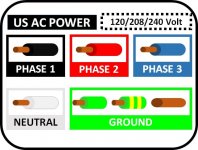
From household wiring, have it in my head that black is "hot", so went with that.
Yes. Black is the color your finger will turn when you touch it.
But that’s AC house wiring.
The PSU is DC, where V+ is typically red and ground typically black.
Attachments
I'm very interested/curious about this volume control solution, would like to ask:
The published specs are pretty spectacular. Do you feel that it is as transparent as the specs would suggest?
Are you using the diyaudio store chassis? Does this volume control fit in the B1K chassis with the encoder installed in the volume control position? It seems like it would just barely fit but only by removing the right angle pins and replacing with straight pins
How did you handle the duplication of Rs and Cs between the output of the pot and the input of the B1B? Did you wire directly to the junction of the 332k resistors of the B1K or remove components from the volume control or use as-is?
I forgot to ask -- does the infra-red system use Sony or NEC IR codes, or is it proprietary? I couldn't find the answer to that on the website, maybe I overlooked it.
It's working!
Should I swap out that resistor with a fresh one?
What about the fact that I'm only getting 9v at the diode?
I'd replace it. For a few cents its worth the peace of mind. If anything you will reflow the solder joint when you swap it out, which might have been damaged depending on how hot that resistor got, averting a future failure.
--Tom
I'd replace it. For a few cents its worth the peace of mind. If anything you will reflow the solder joint when you swap it out, which might have been damaged depending on how hot that resistor got, averting a future failure.
--Tom
Yes, I think I'm going to do that.
I forgot to ask -- does the infra-red system use Sony or NEC IR codes, or is it proprietary? I couldn't find the answer to that on the website, maybe I overlooked it.
Ah, found it -- it's NEC compatible.
Pass DIY Addict
Joined 2000
Paid Member
JASnyder: I would also check your on-board PSU caps. What is their voltage rating and how much voltage did the wrong wall wart hit them with? If it is severely over voltage (ballpark, + 25% or more), there is the possibility your caps - at least the first one - are damaged as well. The CRCRC filtering might have protected the zener.
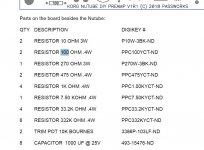
I have started stuffing my PCB and all was going fine until I got to the 100R resistors. I ordered the two specified in the BOM and find that there are four locations for 100R resistors on the PCB and the schematic shows two per channel.
Is there something here that I haven't grasped, or is the BOM simply wrong?
Is there something here that I haven't grasped, or is the BOM simply wrong?
Attachments
Pass DIY Addict
Joined 2000
Paid Member
I don't have a specific answer to your question about an error in the quantity indicated, but the easy thing to do in the future is just buy more than you need. The minimum number of resistors that I order is always 10, sometimes 20. Yep, it costs more up front, but prevents frustration, an additional shipping charge, and waiting the extra week for more parts to come in the mail. Nothing like an $8 shipping charge for $0.20 worth of parts...
There is ALWAYS a next project...
There is ALWAYS a next project...
There is ALWAYS a next project...
Of course!
When I had my own workspace I ordered my MF resistors in quantity 200 where they got really cheap. Have just moved to a retirement community where that approach is not going to work anymore and I left my stash of thirty years back where I came from.
This is my first post-move project, I've made a couple of blunders, the worst is misjudging the height of the Korg chassis so my beloved LDR volume control with display won't fit. And tubes is a whole new world for me so not as confident as I might be, and since there seem to be other "adjustments" on this board (fets & resistors) I thought I'd better ask before moving ahead. But the more I look at the schematic it's pretty clear that all four 100Rs do belong there.
I have ordered the volume control from Academy Audio which needs +/-15vdc that'll have to come from a converter.
Now trying to figure out whether I want an isolated or non-isolated converter to give me the two new voltages. I gather the isolated is preferable for flexible grounding but that version contains a transformer to convert the voltages and I am wondering if it will introduce hum into the preamp.
Any thoughts would be very welcome.
Last edited:
sch could help
this way, too general
properly designed volume control should have isolated control supply from audio gnd/rails
this way, too general
properly designed volume control should have isolated control supply from audio gnd/rails
Pass DIY Addict
Joined 2000
Paid Member
wapo: if you are in need of a few 100R resistors, PM me with your address and I'll drop a few in the mail to you. With any luck, they'll get to you by June 😉
wapo: if you are in need of a few 100R resistors, PM me with your address and I'll drop a few in the mail to you. With any luck, they'll get to you by June 😉
Eric, thank you for the very kind offer!
My order for the resistors is already in -- the resistors and a dc/dc converter for the IR volume control that is also now on the way, plus a couple of other items. I found some 124R mf resistors in my meager pile of spares but decided that timing was not an issue and I'd rather have it exactly right.
I will be using this with a big amp and efficient speakers, is there a way to reduce or tune output level?
I thought maybe some inline resistors or something that would reduce it by 25%, 50%, 75%.
My current amp has input attenuation and I have them turned way down. The amp I am going to does not.
I thought maybe some inline resistors or something that would reduce it by 25%, 50%, 75%.
My current amp has input attenuation and I have them turned way down. The amp I am going to does not.
Yes, you can make an attenuator L pad with two resistors. But it will effect the output impedance after the L pad. Make sure your power amp can handle it without effecting the response.
Yes, you can make an attenuator L pad with two resistors. But it will effect the output impedance after the L pad. Make sure your power amp can handle it without effecting the response.
I'm curious about this also -- my "preamp" up to now has been a zero-gain LDR based control and I've enjoyed that because at normal listening levels in my system the volume control was always between a virtual (digital) 12-o'clock and 3-o'clock position. I don't think I'm going to appreciate the extra 10db or so of gain.
What would be the impact of adjusting the resistors at the output of the Korg by, say, reducing the 33.2K? Although, I suppose the optimum solution would be to keep the signal level high all the way to the power amp and attenuate the signal there?
- Home
- Amplifiers
- Pass Labs
- B1 with Korg Triode