

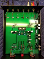
Excellent clear design and confortable space for all components , values writen on the pcb help avoid mistakes ,save time as well.
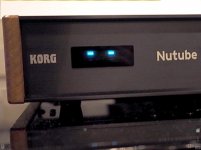
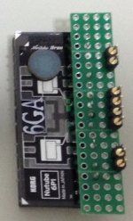
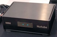
For amateurs who like triodes light glow on the B1T chassis front is easy to make small adaptor with perfored board etc.
Thank You very much Mr Pass
My life is better with audio constructive hobby
For amateurs who like triodes light glow on the B1T chassis front is easy to make small adaptor with perfored board etc.
Thank You very much Mr Pass
My life is better with audio constructive hobby
Attachments
-
 2C61997F-D475-4656-99D1-0D44A0041B45.GIF30.7 KB · Views: 1,397
 -
 1CFF7BB8-2DC8-45AA-9213-99F82E3FB61A.jpg141.4 KB · Views: 1,318
 -
 54400FCD-8969-4CC9-BE45-21E63B89863F.JPG256.8 KB · Views: 1,221
 -
 800A7E9A-C704-4677-B2DD-173371F0245F.JPG47.4 KB · Views: 1,240
 -
 09332858-9044-45DC-B8FD-18168A0938F2.JPG113.9 KB · Views: 1,212
 -
 29571D62-FE27-4BFD-8A8E-932CF043603D.JPG130.5 KB · Views: 510
Last edited:

Kudos and many thanks!!! So this is going to the DIY store? DIYers are a happy lot. Hearing sweet sounds for part of the day every day is a good thing. Read John Stuart Mill on music.
https://www.goodreads.com/quotes/241201-the-art-of-music-is-good-for-the-reason-among
https://www.goodreads.com/quotes/241201-the-art-of-music-is-good-for-the-reason-among
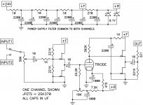
Compared to initial schematic not all resistors is the same for example 3x 332K and 2 times 33.2K only one 7.5K ?
Where is two volume potentiometers soldering pads, source selection on the prototype pcb ? Oh ok is simplified version.
Not two 9.1V zener's ?
If one channel have 2x1000 uF and one 2200uF total of the big audio section caps is 6 pcs not 5.
Any reason for all changes ? Kindest regards 🙂
Where is two volume potentiometers soldering pads, source selection on the prototype pcb ? Oh ok is simplified version.
Not two 9.1V zener's ?
If one channel have 2x1000 uF and one 2200uF total of the big audio section caps is 6 pcs not 5.
Any reason for all changes ? Kindest regards 🙂
Attachments
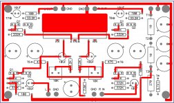


The new PCB layout seems a bit simpler with no input selector on PCB etc. 24 VDC power is the terminal at T1 I guess…..on the new PCB layout?
I like the First Watt pcd layout better.... Won't stop me ordering the new one though.....The new PCB layout seems a bit simpler with no input selector on PCB etc. 24 VDC power is the terminal at T1 I guess…..on the new PCB layout?
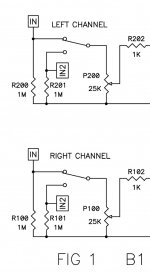
Yes, I also like the FW very much. I assume that the very large area of cu on FW PCB is the ground plane? ...the FW layout is for two mono pots for volumen? …..that is quite special. I would probably use a stereo pot anyway…...
Two mono pots for volume correct small imbalances of the two triodes. A small pcb allows different assemblies.
My 6P1 is coming....
My 6P1 is coming....
None whatsoever.
😛
More funny I do see 22 fixed resistors on the schematic but FW B1Triode have 23 pcs.
Was one resistor who cure differences between two triodes or..?

Was one resistor who cure differences between two triodes or..?
Hi Soundhappy, small differences gain of the two triodes are always present. I think that at the input of the pre the two mono pots for volume have this function.
If you get the thumps, you know what to do....
😛
Thanks a lot Mr Pass.
I stay tuned to the last revision news.
Best regards 🙂
None whatsoever.
😛
Without answer I try find some anyways , do Mr Pass post is the right one about
only one zener and new 100R resistor inside updated pcb B1 Triode version 🙄
Attachments

- Home
- Amplifiers
- Pass Labs
- B1 with Korg Triode