Just to report a successful build. I bought the parts (incl Nutube) from the Diyaudio store, added Takman metal foil resistors and Panasonic FM power capacitors (1000uF and 2200uF) plus Silmic 10uF for the signal path (the latter bypassed with polypropylenes). Finally added a separate, 2 meter removed, psu with a cheap chinese psu and trafo. Everything worked perfectly from day one, absolutely no noise, whatever I did to provoke it (within reason). Now I am waiting for the Meanwell power supply recommended by Laverda, as the effect that Laverda described is the only improvement, I can think of. All in all, a very happy teddy.
Just to report a successful build. I bought the parts (incl Nutube) from the Diyaudio store, added Takman metal foil resistors and Panasonic FM power capacitors (1000uF and 2200uF) plus Silmic 10uF for the signal path (the latter bypassed with polypropylenes). Finally added a separate, 2 meter removed, psu with a cheap chinese psu and trafo. Everything worked perfectly from day one, absolutely no noise, whatever I did to provoke it (within reason). Now I am waiting for the Meanwell power supply recommended by Laverda, as the effect that Laverda described is the only improvement, I can think of. All in all, a very happy teddy.
Can you please report your experience on PP bypassing Silmics? What have you used and did it bring more clarity? I can definitely hear the elcos signature and it starts to bother me
I only bypassed the Silmics because of routine. At some point I have decided that bypassing electrolytics in the signal path makes the sound better (clearer, smother, more open, whatever) - honestly, I have forgotten why. On the other hand, I never bypass power electrolytics as I did not find any change there. For bypassing smaller electrolytics like these, I have settled on Roederstein 0,01uF. All this may sound silly, but I experimented quite a lot many years ago and am still following the routine I established then. Excercising a bit of Maoist self-critique, developments in production/design may have made my routines completely obsolete, but it hopefully wont harm the quality of sound.
Bypassing electrolytics might not make it much better, but it I have not
seen a case where it's worse.

seen a case where it's worse.
It is interesting to calculate (or measure) the impedance of the bypass capacitor compared to the ecap or the change in impedance ecap alone compared to ecap + bypass cap. It is usually close to "nothing"......even at relative high frequencies.
Just to report, that the Meanwell RS-75-24 works very well with the B1 Nutube. The sound is remarkably good!
Unfortunately, I can´t do an immediate A-B comparison and to compare with the sound of a linear power supply with an hours delay is not reliable, so not really. With that caveat, the sound does however compare well with my ususal setup (a fully passive preamp with a transformer volume control).
I was testing our a new sine wave generator and measured my Schiit Freya Preamp that has a tube stage option that provides some gain. It sounds "tubey" for sure. I took this measurement of it to see the harmonics.
The second picture if from the B1 Nutube and you can see it has way more harmonics than the tube stage of the Freya.
It's cool to see what you can do with DIY compared to a $800 commercial preamp.
The second picture if from the B1 Nutube and you can see it has way more harmonics than the tube stage of the Freya.
It's cool to see what you can do with DIY compared to a $800 commercial preamp.
Attachments
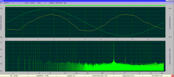
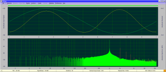
Are you saying the Nutube is too "tubey" sounding? I'm not good enough at this yet to interpret either your statements or the graphs.The second picture if from the B1 Nutube and you can see it has way more harmonics than the tube stage of the Freya.
No the B1 Nutube is not too tubey. I use the B1 as my preamp over the Schiit preamp because I think it sounds better.
I'm no expert either but I think some say that the harmonics are what make it more tube sounding.
I'm no expert either but I think some say that the harmonics are what make it more tube sounding.
Thanks for sharing this Mrshazbot
To give this measurment its full meaning, could you please specify:
- what reference level in V you have for your 1k signal at the output?
- what voltage setting you went for with the trim pots re H2 level (Papa's 9.5V... or else - I remember you lentioned 11.4V in one of your older posts using Diana)
Thanks again!
Claude
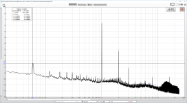
Note: quite a lot of lower frequency and presumably intermodulation noise... PS or measurement?
To give this measurment its full meaning, could you please specify:
- what reference level in V you have for your 1k signal at the output?
- what voltage setting you went for with the trim pots re H2 level (Papa's 9.5V... or else - I remember you lentioned 11.4V in one of your older posts using Diana)
Thanks again!
Claude
Note: quite a lot of lower frequency and presumably intermodulation noise... PS or measurement?
It's just under .7v out. For some reason my Focusrite doesn't like a higher output. It used to take it but it won't anymore.
I tuned it back to 9.4v per the recommended setting.
I don't know what intermodulation noise looks like. Is that the 60 hz / 180 hz, etc from the PSU? I finally got REW working so it's more obvious.
Initially my preamp had a hum from some bad grounding but it's quite now on 89 db speakers.
I tuned it back to 9.4v per the recommended setting.
I don't know what intermodulation noise looks like. Is that the 60 hz / 180 hz, etc from the PSU? I finally got REW working so it's more obvious.
Initially my preamp had a hum from some bad grounding but it's quite now on 89 db speakers.
Attachments
Thanks again 🙂
TBH I am not a specialist of these kind of things, merely trying to understand as an (old) engineer who gets started again with his hobby.
All I can say is that the 2 graphs are "generaly" not "that" different to my eyes, once you take into account that the 2nd measurement starts at -6.6dB vs 0dB ref and that it has a log vs linear X axis. The second graph seems cleaner especialy around the 1k signal, and differs also quite a bit in terms of harmonic peaks after H4 and high frequency noise...
What may (or not may? LOL) be remarquable, is:
- General noise floor higher below 2k than afterwards, say 10dB difference, in both cases
- Quite some PS peaks at 60Hz and harmonics, say up to 540Hz
- Signal harmonics probably as expected on 2nd graph, less so on first (H4 and H5)?
- Wonder what these peaks around 8k and 16k are on the second graph - they are not identified as harmonics though, but quite outstanding
- Wonder what the noise is from say 12k to 25k on the second graph (filter, measurement, reality?)
Having said all that, it is again not a disaster at all as generaly speaking the values are not bad and general behaviour is as expected I guess! More me just thinking loud: I love trying to understand the graphs and the truth behind them and the measurmeent process, perhaps someone can help?
Have a very nice day
Claude
I'm a recovering over analyzer 🙂 so I try to stop myself from tinkering too much with it. My skill level is also such that I have an equal chance of fixing or breaking it if I mess with things too much. It also sounds fine to me which is what matters the most.
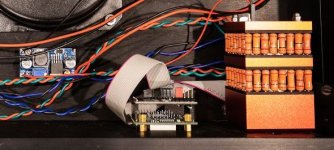
My volume control requires 5V and .5A so I have 24V from the PSU to a cheap buck converter that cost like $2 from Amazon (which is stupid because the remote controlled volume costs way too much) and that provides power to the vol control. I've assumed that is part of the not so perfect measurements but the only way to check is to swap out a basic volume knob and test but again, if it sounds good I don't want to break anything.
Thanks for your interpretation of the measurements, it's helpful for my learning.
Attachments
I'm a recovering over analyzer 🙂 so I try to stop myself from tinkering too much with it. My skill level is also such that I have an equal chance of fixing or breaking it if I mess with things too much. It also sounds fine to me which is what matters the most.
My volume control requires 5V and .5A so I have 24V from the PSU to a cheap buck converter that cost like $2 from Amazon (which is stupid because the remote controlled volume costs way too much) and that provides power to the vol control. I've assumed that is part of the not so perfect measurements but the only way to check is to swap out a basic volume knob and test but again, if it sounds good I don't want to break anything.
Thanks for your interpretation of the measurements, it's helpful for my learning.
I'm not sure I understand your volume control. From what I see in the pic you have very nice(expensive) ladder volume pot. How do you remote control it? Is it motorized?
Would you allow a link to the information on that volume control just in case I hit the lottery today and can afford to include it in my build?
I believe it's a Khozmo attentuator.
Interesting! I know Khozmo from way before, didn't know he makes remote controlled now.
In my humble opinion with that kind of investment in pot Mrshazbot should absolutely stretch some more and put quality solid caps in place of 3 10uf pairs, to have truly high end build and sound...
- Home
- Amplifiers
- Pass Labs
- B1 with Korg Triode