Here +-1% is generally good enough.
So that would make the 1K2 and the 820R less than ideal coming off the pot.
Sent from my GT-I9505 using Tapatalk
What effect on performance will changing from 1k to 1k2 have?
That 20% change may make no difference to performance other than changing the voltage.
This is a DESIGN analysis, not a bit of guesswork.
That 20% change may make no difference to performance other than changing the voltage.
This is a DESIGN analysis, not a bit of guesswork.
When I was asking for analysis, I was picturing something like: the R103 impedance affects the operation of the JFETs this way. .. and so the specd value is fairly precise; OR the R103 merely acts on the pot output this way... and so the value could be changed within this range without much effect; OR the R103 works together with the trimpot and so if it's value changes, the trimpot value might need to change to....
Since you gave a general statement about tolerances in this circuit, I don't know how to understand your use of the word analysis vs guess. In my world, analysis of interactions and values moves toward prediction.
Sent from my GT-I9505 using Tapatalk
Since you gave a general statement about tolerances in this circuit, I don't know how to understand your use of the word analysis vs guess. In my world, analysis of interactions and values moves toward prediction.
Sent from my GT-I9505 using Tapatalk
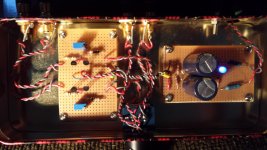
Curious about those pics. Are there a few more parts on the buffer than the Rev2? It looks like you used the spec'd DC power smoother and voltage divider even with the Salas shunts, which look like two rails? Would that be strictly speaking redundant?
Yes, the power smoothing caps are probably redundant but they can't hurt. The extra parts are the power supply for a input switching relay. Unnecessary, I know - I just felt like doing it.
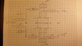
OK, I’ve done a layout and assembled parts, but could use some feedback as it’s my first DIY layout, and also have some specific newbie questions:
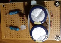
Power module:
Preamp circuit:
Any other issues that will help avoid noise here?
Power module:
- 10R at DC entry is wirewound 3W
- Resistors on DC output after cap are metal film ½ watt, as is the resistor on the LED. Because they are 4.75K Ohms it seems 1/2 watts is fine and wirewound not so much an issue here?
- Caps are Panny FC (low ESR), though I have some Nichicon FW available.
- I’m using stripboard, 50mm x 80mm, and nearly all the strips are used, except for edges. I’m hoping the distance between strips is enough that noise will not be an issue? Technically, no spots needed to be cut in the strips.
- Because stripboard holes are 1mm, the input and output from the board are 22AWG solid core pairs, as nothing larger than 20 would fit anway. I’m hoping that is robust enough for optimal power delivery? I suppose I could solder an 18AWG between the 1A DC power supply directly to the 10R resistor leads. The current reqs are meant to be pretty low.
- The power termination blocks available all seem to require 1.3mm holes, so it seems would not be fit for purpose.
- Jumpers (2x) on right serve to common the cap centre leads, which goes to circuit Common. The zip tie (temporary) mostly hides one of them.
Preamp circuit:
- I put Right & Left as facing mirrors of each other, and the power in is a solder point in the centre, between the JFETs same wire as above, twisted pair.
- Again stripboard was used 50mm x 80mm. Spots are cut in the strips at relevant places across the centre between channels.
- On attached, vertical lines connections supplied by strips, horizontal lines are supplied by leads, and curved lines are supplied by jumper wires.
- Since I'm starting with only one output and won't have a switch, I assume the 1M resistors on the input & output positives are not needed?
- I would expect to connect preamp Common directly to power module Common, along with Potentiometer and RCA Earths.
Any other issues that will help avoid noise here?
Attachments
0.5mm diameter copper has a current rating of >600mA and for transient duty could probably cope with 2 to 3Apk.
You don't need 18awg (swg) cabling.
0.6mm diameter hook up wire in low temperature PVC insulation can take about 1A continuous and never get warm enough to soften the PVC.
You don't need 18awg (swg) cabling.
0.6mm diameter hook up wire in low temperature PVC insulation can take about 1A continuous and never get warm enough to soften the PVC.
I don't follow your layout drawing.
The input for one channel is a TWO WIRE connection. I can't see any two wire input.
The output for one channel is a TWO WIRE connection.
Same for the other channel.
You should have four two wire connections going In/Out of this board.
The input for one channel is a TWO WIRE connection. I can't see any two wire input.
The output for one channel is a TWO WIRE connection.
Same for the other channel.
You should have four two wire connections going In/Out of this board.
Yes sorry, I did not show the wiring of the input & output RCA’s or the volume pot, just showed the layout of the boards. I was presuming that the preamp board would handle the Signal-wire side of things, and the Signal Earth In/Out would not need to have any connections on the actual board. It would go from RCA In > Vol Pot > RCA Out and merely be twisted with the Signal wire, without an actually connection to the board. Is there a reason it should? I suppose that could complicate the wire pair twists…
Or am I missing something more basic?
Or am I missing something more basic?
I built the B1r2 about three weeks ago with an Alps Blue Velvet and put it in a biscuit tin for my proof-of-concept phase, powered from a SMPS laptop supply and the simple voltage divider.
Amazing! For just a handful of parts I'm getting some pretty amazing sound, which beats a lot of what I've heard including.
Really silent and sound emerge with a natural ease. There are good details and imaging, even at lower volumes. There is just such a musical-ness and breath of life in its presentation, a realistic sense of space between the musicians that doesn't seem to be just about staging depth and separation. I also got a bit more bass, low and high bass, so had to move the speakers a little to rebalance with the room.
A few experiences with the biscuit tin: being flimsy, chassis vibration is a delicate issue. With no damping, things were just a bit nervous and congested in lively, complex music. Add some Silent Coat 2mm butyl-based damping and everything went a bit over the top in the euphonic department, but lost all the harmonics and leading edge of sounds. Dropped back to just two 1cm squares with a little experimentation on placement.
It's sounding pretty good now, way better than I could imagine for the cost and use of an SMPS, but it's time to put in a proper enclosure and build a proper linear supply and see what that does to the sound.
Attachments
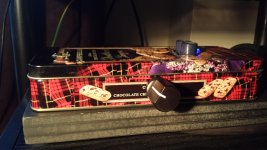
Congrats and nice work. Before any more time passes, use either electrical tape or a rubber grommet to protect the DC line coming in the box. Wont take much to short it.
Nice job.
Vince
Nice job.
Vince
Congrats and nice work. Before any more time passes, use either electrical tape or a rubber grommet to protect the DC line coming in the box. Wont take much to short it.
Nice job.
Vince
Yes, should do in the next day. BTW: I should have drilled with a wood backing behind the tin, as it's way too easy for the bit to tear the hole. The whole things is way too rough to keep for long, but I should have a proper enclosure in a couple weeks. The RCA's balked at being mounted to a panel that thin. I think their minimum was 1mm.
Interestingly, when I attached the chassis to true earth (shield), it sucked all the life and dimension out of the music. Perhaps because the circuit common is floating inside? Not much shielding possible with panels that thin anyway.
Ha! I made a headphone amp in a tin like this once - I still use it occasionally. Looks nice. I'd recommend a shunt supply like Salas' SSLV over a linear one, though a good linear supply can do the trick.
I'm thinking you should be able to run the shunt regulator after the switchmode and still get 100% of the performance of the Shunt reg. That's untested of course, just my brain visualising it.
I usually shunt 3 x bias current.
I usually shunt 3 x bias current.
If adding a Buffer improves the sound at all, it shows that your previous system connections were flawed.I built the B1r2 about three weeks ago with an Alps Blue Velvet and put it in a biscuit tin for my proof-of-concept phase, powered from a SMPS laptop supply and the simple voltage divider.
Amazing! For just a handful of parts I'm getting some pretty amazing sound, which beats a lot of what I've heard including.
Really silent and sound emerge with a natural ease. There are good details and imaging, even at lower volumes. There is just such a musical-ness and breath of life in its presentation, a realistic sense of space between the musicians that doesn't seem to be just about staging depth and separation. I also got a bit more bass, low and high bass, so had to move the speakers a little to rebalance with the room.
A few experiences with the biscuit tin: being flimsy, chassis vibration is a delicate issue. With no damping, things were just a bit nervous and congested in lively, complex music. Add some Silent Coat 2mm butyl-based damping and everything went a bit over the top in the euphonic department, but lost all the harmonics and leading edge of sounds. Dropped back to just two 1cm squares with a little experimentation on placement.
It's sounding pretty good now, way better than I could imagine for the cost and use of an SMPS, but it's time to put in a proper enclosure and build a proper linear supply and see what that does to the sound.
What was the flaw? Insufficient current capability, inappropriate output impedance, or bad cables?
thin shielding and holely shielding both work.Yes, should do in the next day. BTW: I should have drilled with a wood backing behind the tin, as it's way too easy for the bit to tear the hole. The whole things is way too rough to keep for long, but I should have a proper enclosure in a couple weeks. The RCA's balked at being mounted to a panel that thin. I think their minimum was 1mm.
Interestingly, when I attached the chassis to true earth (shield), it sucked all the life and dimension out of the music. Perhaps because the circuit common is floating inside? Not much shielding possible with panels that thin anyway.
Think how thin the foil shield is on a coax cable, think how holely the braided shield is on a coax.
Have you seen a room sized Faraday cage. It's full of holes !
If adding a Buffer improves the sound at all, it shows that your previous system connections were flawed.
What was the flaw? Insufficient current capability, inappropriate output impedance, or bad cables?
Sure, one could say the secondary leads from the transformer were compromised and could not deliver the current necessary from the windings.
However, are you saying anything beyond the basic idea that any preamplifier which sounds better than another implies flaws in the other?
He's saying a buffer should not sound like anything. Anything bad you hear is the fault of what's before the buffer or what the buffer replaces.
The idea is like having a volume pot with good input and output impedance matching. Also as stated in the original B1 article & paraphrasing- Source gear has a lot of gain. A preamp with gain is just throwing gain away. A buffer just uses what the source has to offer. With the exception of some phono stages, a buffer is enough.
The idea is like having a volume pot with good input and output impedance matching. Also as stated in the original B1 article & paraphrasing- Source gear has a lot of gain. A preamp with gain is just throwing gain away. A buffer just uses what the source has to offer. With the exception of some phono stages, a buffer is enough.
Last edited:
So here is the thing... (More rhetorical). There are som cool stuff Nelson does with new outputs: F7, xa25, DEF, sit, you name it. However, here we are decayed later with nothing actually to replace j74/k170. I know "lsk" parts are here, but still kinda pain in the ... get them, match, price is high and all the fakes for toshibas. Really nothing interesting came around since then? Juma uses bf862 and they can be used as a drop in (more or less) for b1, but what abot p-channel pair for it?
There are two things here: 1. Just curiosity about new cool parts to try and; 2. Sometime you just need a simple not very critical buffer and don't want to go through all these trouble with our beloved k/j couple 🙂.
There are two things here: 1. Just curiosity about new cool parts to try and; 2. Sometime you just need a simple not very critical buffer and don't want to go through all these trouble with our beloved k/j couple 🙂.
- Home
- Amplifiers
- Pass Labs
- B1 Rev. 2