Ok, just continuing the + and - signals without removing the common mode noise at the input. Where is the schematic for the balanced iron pre?

Folks:
Some advice, please. I'm planning a B1 R2 project and need to size the transformer. Because of height limitations (a 1U chassis), a low-profile approach is needed. I'll be using one of Mark Johnson's VRDN boards as the B1 R2's power supply. My question: will a Hammond 229B24 transformer (12VA, 12 VAC @ 1A) be adequate to power the buffer? An alternative is Hammond's 229C24 (24VA, 12 VAC @ 2A). The only other load on that power supply will be 14 white LEDs, drawing about 1.5 mA apiece.
Other suggestions are certainly invited.
Regards,
Scott
myleftear:
Yup, I hear you. But I may not need tall heatsinks if the voltage in is fairly low. I want 12 VAC out of the VRDN. After rectification, 12 VAC secondaries will get me roughly 16 VDC, so the VRDN won't be dissipating much. I'll look for suitable heatsinks.
But how much wattage do I need? I don't want to stress the transformer. Is 12 VA suitable?
Regards.
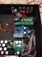
I built a VRDN to supply a FE2022 preamp. Given the current draw was nowhere near the full capability of the board, I cut the heatsinks down so that they were approximately the same height as the capacitors. Fits nicely in a small Galaxy and has worked without issue for > 1 year:

In the Iron Pre thread, ZM was of the opinion that small toroidal power transformers are more prone to instability under a varying load. I suppose that makes sense when one thinks about the energy stored magnetically in the toroidal core. Thus if the 24VA fits it might be a better bet even if the B1 R2 is only sipping power.Folks:
Some advice, please. I'm planning a B1 R2 project and need to size the transformer. Because of height limitations (a 1U chassis), a low-profile approach is needed. I'll be using one of Mark Johnson's VRDN boards as the B1 R2's power supply. My question: will a Hammond 229B24 transformer (12VA, 12 VAC @ 1A) be adequate to power the buffer? An alternative is Hammond's 229C24 (24VA, 12 VAC @ 2A). The only other load on that power supply will be 14 white LEDs, drawing about 1.5 mA apiece.
Other suggestions are certainly invited.
Regards,
Scott
I use a wall wart transformer. 1A 16VAC. Works great! And the big AC volts and transformer field stays far from the signal.
Single rail.... But you could do a half bridge rectifier on that which is what I do. I get plus minus 12 out of mine with it. Jameco has the transformer. They have a few like that. I'm at at a brewery with buddies right now. PM me and I'll send you all the details later. It works well.
The B1 draws probably 10 to 15mA per channel, and that would include LEDs and power supply bleed resistors. It is Class A so the current draw is fairly constant.
The Hammond 229B24 (24VAC center tap at 500mA) is more than adequate.
Triad also makes a transformer that would probably work too: https://www.mouser.com/ProductDetai...T*MTczMDA2ODk1OC4xLjEuMTczMDA2OTk2Ny41Mi4wLjA.
I have a Triad transformer of this series in my DIY FE 2022 preamp as part of a linear power supply, all mounted in one chassis with no issues at all.
Ben Mah:
Thank you!
ranshdow:
Just to be clear, the Hammond 229B24 is a low profile PCB mount transformer (dual split bobbin) as opposed to a toroid. That said, I wouldn't be averse to a toroid, except it happens that the Hammond is less expensive with seemingly very low emissions.
Thanks to all for the support!
Regards,
Scott
Folks:
What hubris! I thought this project was too easy for me to mess up. I'm working on the first of two B1 projects; this one is a Rev. 2, and it appears something is amiss on the B1 Rev. 2 pcb. Here are readings taken from the Left and Right RCA inputs to the inputs at the B1 pcb:
All of the above seemed fine to me, so I next measured from the Left and Right RCA inputs to the outputs on the B1 pcb:
I found this confusing, so I then measured between the inputs and outputs on just the B1 pcb:
When installed in a system, the Left channel operates but is unaffected by the attenuator -- it's playing at full volume. The right channel is silent. There are presumably at least two problems at work here. The power supplies (regulated 5VDC for the attenuator system and a VRDN for the B1 Rev 2) are working properly. Can anyone help me diagnose what's up?
Regards,
Scott
What hubris! I thought this project was too easy for me to mess up. I'm working on the first of two B1 projects; this one is a Rev. 2, and it appears something is amiss on the B1 Rev. 2 pcb. Here are readings taken from the Left and Right RCA inputs to the inputs at the B1 pcb:
Left Channel | Right Channel | |
| B1 off | ||
Input L at B1 pcb | 22.91k | 1.02M |
Input R at B1 pcb | 1.03M | 22.8k |
| B1 powered on, attenuator set at -63 db | ||
Input L at B1 pcb | 23.6k | 1.03M |
Input R at B1 pcb | 1.03M | 23.6k |
| B1 powered on, attenuator set at 0 db | ||
Input L at B1 pcb | 0.6R | 1.03M |
Input R at B1 pcb | 1.03M | 0.8R |
All of the above seemed fine to me, so I next measured from the Left and Right RCA inputs to the outputs on the B1 pcb:
Left Channel | Right Channel | |
| B1 off | ||
Output L at B1 pcb | 1.01M | 23.8k |
Output R at B1 pcb | 1.02M | 23.5k |
| B1 powered on, attenuator set at -63 db | ||
Output L at B1 pcb | 27.26k | about 24k (reading vacillates) |
Output R at B1 pcb | 1.03M | 23.7k |
| B1 powered on, attenuator set at 0 db | ||
Output L at B1 pcb | 25.5k | about 22.4k (reading vacillates) |
Output R at B1 pcb | 1.01M | 164R |
I found this confusing, so I then measured between the inputs and outputs on just the B1 pcb:
Left Channel | Right Channel | |
| B1 off | 705k | 610R |
| B1 powered on, attenuator set at -63 db | 25.5k | 145R |
| B1 powered on, attenuator set at 0 db | 25.5k | 163R |
When installed in a system, the Left channel operates but is unaffected by the attenuator -- it's playing at full volume. The right channel is silent. There are presumably at least two problems at work here. The power supplies (regulated 5VDC for the attenuator system and a VRDN for the B1 Rev 2) are working properly. Can anyone help me diagnose what's up?
Regards,
Scott
Attachments
@SRMcGee Lots of pieces there, and they all interact.
Ok, let’s break it down a little and verify that each widget is operating as you expect. You’ve got power, very good, step one done.
Get out the solder wick, the desolder pump, and the flux, you've got a bunch of various, temporary connections to try.
1) The input selector can be tested in situ - are all connections working, is the switch switching they way you expect? Test all nodes and verify.
2) Attenuator - disconnect from the buffer and selector switch and run a signal directly to the input and test the output, is it attenuating as expected?
3) B1 buffer. If the selector switch is operating properly, put signal directly into B1 without the attenuator attached and see of B1 is working properly. If the sector is wonky, test B1 anyway to cross it off the list.
If all these pieces operate normally by themselves, then it’s just a wiring mistake.
But until you verify all the parts are operating normally, wiring can’t be diagnosed.
6L6:
Thanks for calming me down!
I followed your guidance; the input selector worked in situ, the attenuator attenuated and the two worked together as they should. I spent a ridiculous amount of time pouring over the B1 pcb before spotting the tiny soldering slop that was causing all the trouble. What a maroon (credit to B. Bunny)!
Seriously, thanks!
Now on to the second B1 variant. If history is a guide (and it most certainly is), I'll be back with another dopey problem or two.
Regards,
Scott
- Home
- Amplifiers
- Pass Labs
- B1 Rev. 2