Did some reading - for the Super Regulator, keep the B1 R2 Power Supply Filter. It is recommended that the capacitors are not low ESR.
https://www.diyaudio.com/community/threads/super-regulator.247281/post-7016031
In the end, it all depends on your power supply. If your power supply is clean and has a reasonable amount of capacitance at its output and the power supply is located next to the B1 board, then the added capacitance is probably not required.
Another power supply choice is to go with a SMPS and filter its output with Mark Johnson's SMPS DC filter:
https://diyaudiostore.com/products/smps-dc-filter-p089zb-kit
https://www.diyaudio.com/community/...all-warts-preamps-hpa-korg-nutube-etc.354213/
The SMPS DC Filter output then goes into the B1 R2 Power Supply Filter.
https://diyaudiostore.com/products/smps-dc-filter-p089zb-kit
https://www.diyaudio.com/community/...all-warts-preamps-hpa-korg-nutube-etc.354213/
The SMPS DC Filter output then goes into the B1 R2 Power Supply Filter.
I’m trying to keep at simple as possible to get started, SMPS filter might be a good option. Then I can upgrade to a better PS later. That filter just cleans up the SMPS?
No need to go all in with the PS. The B1R2 uses very low noise FETs and has no gain so noise is not amplified either. A good enough PS with good filtering is all you need. I use an AC wall wart with a half bridge, CRC and MC7x12 regulators all layed out on the same board and it sounds great. Just pay attention to rectifer vs signal ground path layout and it will be as good as it needs to be. ... and @gac800 I just read the bit about you wanting to keep it as simple as possible, so nevermind. But if you did not get a PCB yet I can send you a pretty fully featured single board B1RS preamp PCB with BOM if you want. It has an easily bypassed op amp gain stage if you want a pure B1R2. The wall wart AC transfomer cost about $11 from Jameco,


This is the previous rev populated. It's all you need, really. Well, it's all I'llever need anyway. B1R2 is the bomb! Such a great buffer that lends itself tto many uses.

That board looks great. I am probably going to go in a similar direction with additional filtering before the b1r2.
what part of this board is splitting the voltage into +/-?
what part of this board is splitting the voltage into +/-?
Last edited:
If you look you will notice this board also has mount points for phoenix connectors in case you want to use external power or RCA jacks.
I built it both ways with the external supply being Thatcher's Pearl 3 supply with full wave rectifier and 1.5x the bulk capacitance. There was no audible difference. Good enough is, oddly enough, good enough. If you want a board you can have one, All I'd want is shipping. Or, hand delivery at Burning Amp! PM me if interested.
I built it both ways with the external supply being Thatcher's Pearl 3 supply with full wave rectifier and 1.5x the bulk capacitance. There was no audible difference. Good enough is, oddly enough, good enough. If you want a board you can have one, All I'd want is shipping. Or, hand delivery at Burning Amp! PM me if interested.
It seems I still need a way to split the voltage into +/- before the regulator?A good clean supply is Jan Didden's Super Regulator:
https://www.diyaudio.com/community/threads/super-regulator.247281/
https://diyaudiostore.com/products/super-regulator
The B1 R2 Power Supply Filter would not be needed, although perhaps more capacitance is not a bad thing - best to read the Super Regulator information.
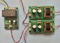
This does not need a 'split'. It uses a bipolar supply. The jack to the lower left is 5.5mm jack for a 12~16V AC input that comes from an inexpensive 1A wall wart transformer. The rectifier for +/- is a half bridge. See the two diodes in the middle of the cap bank below the big green vertical resistors (the 'R' in the CRC). I've put this on an AP. Noise and distortion are insanely low. In the weeds noise floor stuff. The curcuits uses a +/- supply. Not a split with a virtual ground. BTW, the transformer also has a Quasimodo derived snubber on it.That board looks great. I am probably going to go in a similar direction with additional filtering before the b1r2.
what part of this board is splitting the voltage into +/-?
Oh ok, I didn’t realize a wall wart could give you a bipolar A/C supply. I thought they only gave unipolar DC.
I found the AC/AC transformer on the Jameco site, so I understand how it works now. Thanks
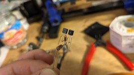
Time ago when I assembled my Balanced Iron Pre I thought to try to change the Cinemag with Edcor iron, but The Iron Pre sound so good as is that I never done this.
When recently I had to make a small preamp for my second system I thought to make the B1R2 and then I thought this was the time to use these trasfomer that I have lying around for already long time
So, in the hope that mighty ZenMod will forgive me for this blasphemous attempt 🙏, here is my version of B1R2 with Iron.
Attachments

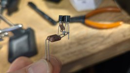
Hi Andy, I've often wondered about adding extra resistance to the j74 jfet (source?) to "match" transconductances of them both but it doesn't seem to be of any significance, no?
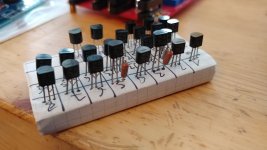
I'm currently building the B1 rev2, and that's exactly what I'll be doing. Actually, I've been doing that ever since I read EUVL's treatise on "Complementary small signal JFETs for F5 input stage". TLDR: 5R source resistor for a 2SJ74 with about 0.8mA higher Idss than the 2SK170.
I just pick a pair of J74's, measure each J74 Idss with a 5R source resistor in place and find suitable K170's to pair up with.
Attachments
Last edited:
Well, that was faster than expected.

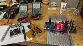
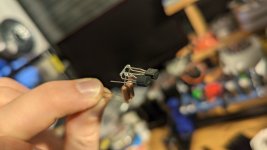
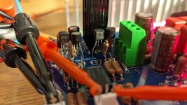
I used a previously abandoned DCB1 Hypnotize build as a base and got busy. Adding an extra LED to the Vref string now results in +10.73V/-10.74V regulator output. The CCS draws about +/- 100mA with 10R wirewound resistors, so it's mildly hotrodded. Here's a closeup:

Grafting the degenerated 2SK170/2SJ74 pairs into the circuit took some effort. Matching also took some effort, but I managed to build the B1 rev2 buffer without a pot. At the output there are just two JFets, a 5R degeneration resistor and a 47R5 output resistor. I'm getting 5-6mV offset from a cold start. Maybe I'll tinker with the Vref LED string of the negative supply to see if I can get the offset closer to zero.
I'm currently listening to the B1 rev2 and it sounds... crisp. Maybe it's just the lower output impedance, who knows 🙂
I used a previously abandoned DCB1 Hypnotize build as a base and got busy. Adding an extra LED to the Vref string now results in +10.73V/-10.74V regulator output. The CCS draws about +/- 100mA with 10R wirewound resistors, so it's mildly hotrodded. Here's a closeup:
Grafting the degenerated 2SK170/2SJ74 pairs into the circuit took some effort. Matching also took some effort, but I managed to build the B1 rev2 buffer without a pot. At the output there are just two JFets, a 5R degeneration resistor and a 47R5 output resistor. I'm getting 5-6mV offset from a cold start. Maybe I'll tinker with the Vref LED string of the negative supply to see if I can get the offset closer to zero.
I'm currently listening to the B1 rev2 and it sounds... crisp. Maybe it's just the lower output impedance, who knows 🙂
Attachments
I have found that varying the voltage between neg and pos is a very inefficient way of affecting offset. There is practically no difference. Hence I had to use use very well matched devices to avoid a pot. Still there is 1,8mV of offset. Liveable.
Is there a way to make a balanced version of the b1r2?
Right now I am thinking of running the balanced input through a transformer, then through x2 b1r2. one for positive and one for -
Right now I am thinking of running the balanced input through a transformer, then through x2 b1r2. one for positive and one for -
Last edited:
- Home
- Amplifiers
- Pass Labs
- B1 Rev. 2