1 + 2)Use batteries instead of a switch mode power supply. Everything else will be virtually the same. You could definitely use a switch mode power supply (also simple to add) but batteries are technically better while also being simpler. I can draw it later if necessary.
you could also have it so it can run on both if you want.
Switchmode is perfectly fine but batteries are better. I would probably include both options if it were me but run it off the batteries most of the time.
you could also have it so it can run on both if you want.
Switchmode is perfectly fine but batteries are better. I would probably include both options if it were me but run it off the batteries most of the time.
Last edited:

1) how much power does this B1R2 typically require under load?
I'm okay with doing a good job on this if it helps me get a great sounding buffer. I'm okay with it taking a bit longer if I have something that will be less hassle long term-- in other words... i'm not into super complexity but it doesn't have to be super super simple.
Thanks again.
It only requires a supply capable of 200mA, less actually, (the circuit will draw a fraction of that) but having more output capability will mean you can use it for more projects into the future.
It's class A, you would have to be driving something pretty demanding to get it into push pull territory. The circuit will draw not more than 40mA.
I would aim for at least 1A capability.
I think I have covered it all very briefly. If you need further explanation on anything, just ask.
Less questions will probably get longer answers.
Last edited:
Inglorious basterd also ok?You can call me numb skull, dumb dumb, pico, or bastard

By the help of the experienced Toxically masculine inglorious basterd Pico, this will be subject for testing during the Christmas days.
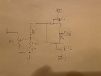
JFETs are matched within 0,01mA, so the pot goes out and degen with it. Exciting stuff.
B1 beast builders V1
Mighty: yes, yes, I know: you did it 15 years ago. But a greenhorn needs some joy
JFETs are matched within 0,01mA, so the pot goes out and degen with it. Exciting stuff.
B1 beast builders V1
Mighty: yes, yes, I know: you did it 15 years ago. But a greenhorn needs some joy
Attachments
It should be stated that the amp has it's own dc blocking cap, just to avoid someone having an aneurysm
Yes, this will be used with the F2J with stock values, and the Aleph J Zen with C1 installed.It should be stated that the amp has it's own dc blocking cap, just avoid someone having an aneurysm
Probably best not to try this with some other constructions.
F5 Turbo with diodes and Iq close to diode conduction point and miniscule sinks, into 1 ohm speakers, may be one of those cases where this should not be tried
It only requires a supply capable of 200mA, less actually, (the circuit will draw a fraction of that) but having more output capability will mean you can use it for more projects into the future.
It's class A, you would have to be driving something pretty demanding to get it into push pull territory. The circuit will draw not more than 40mA.
I would aim for at least 1A capability.
I think I have covered it all very briefly. If you need further explanation on anything, just ask.
Less questions will probably get longer answers.
THANK YOU Pico (I appreciate the option set for names 🙂
Thanks for all the advice.... it helps me get going on this project. Thank you andynor also!
A few more build questions--volume and trim:
-- any suggestions for very good volume control 25K on the B1R2 (2019version)? (I would like it to be quality sounding... I'm not after spending hundreds on some fancy one but if there are really good ones for under maybe 30 dollars or so? (Not sure what's reasonable). It seems like an important part that is in the signal path.
-- trimpots? the schematic shows a 50 ohm trimmer resistor (or whatever you call it). Parts manufacturers often carry Bourne.. but any suggestions since this is directly in the signal path? What are some really good ones? (I might reduce the 50ohm to much smaller if I can get the Idss to balance as well as reduce the 100 ohm output resistor-- suggestions Zen Mod has made earlier).
thanks!
Again Newbie Build questions-- switching inputs and perfboards
Thanks so much for getting me going on this (especially pico and twocents).
-- any suggestions on a switch that allows me to select between 2 RCA inputs (B1R2-2019version)?
-- any suggestions for perfboards-- style and size? I'm going to try point to point wiring and I'm curious of anyone could suggest a size for the project perfbaord? (I plan to have the power supply filter duplicated on each channel... with some space in between each channel so as to have 2 rather independent channels).
Thank you all so much!
Any sealed switch with gold or silver contacts from a reputable manufacturer purchased from digikey etc do not buy anything off ebay unless you either personally know the person or have been referred by another member here.
That goes for all your parts that matter.
That goes for all your parts that matter.
@audiosteve the link is fine, but you may get a security warning from your browser when you try to use the download. I'll see if I can get that sorted somehow. EDIT: In the mean time, check what your download log in the browser says, you may be able to accept the download there.
@Mikerodrig27 There are pre-made Gerbers in the file that you can send to a boardhouse directly, and they should preview with a Gerber-viewer and import into ordering programs from board houses directly. There are also renderings of the gerber-files made with circuitpeople.com.
There are also the "raw" layout files if you want to make changes to the layout. These files are Eagle .brd/.sch-files and you should be able to import them into Kicad, but as I don't use Kicad myself (yet...) I can't tell you exactly how it works.
HTH!
Last edited:
B1 R2 beast builders R1
Three parts per channel.
DC offset: 1,3mV and 2mV, JFETs matched within 0,01mA
Now for connection to F2J. Imminent explosion will be reported.
Zero degen, no pots, no series output resistor.
Attachments

Last edited:
For the record: this was a mod extremely well worth the effort! Increased liquidity and dynamics, just as Pico promised.
My WLS is up for sale, that’s how good it is!!
Will post revised circuit tomorrow. Thanks to Pico and MZM, and Papa of course!
Board isn’t even cleaned, JFETs arent even soldered. Still insane.
Lot’s of potential for chassis layout improvements, and probably also for the B1 board itself. But for now, I’ll just enjoy it like this for a while 🙂
- Home
- Amplifiers
- Pass Labs
- B1 Rev. 2