Hi B1R2 crew. My B1R2 has been running nicely on laptop supply using voltage splitter. Now planning for upgrade. Have Salas Ultrabib boards and minikits. Option 1: one +24 rail into current voltage splitter. Option 2: two rails +12/-12 into voltage splitter. Option 3: two rails bypassing splitter directly to buffer circuit. Any opinions as to best option, or pitfalls?
My current thinking is: Can't see much difference between 1 and 2, given ground as relative, and a bit more filtering can't hurt, which suggests 1. But, channel separation can't be bad either, so 3 could have benefits. Currently leaning towards 1, but open to alternatives.
My current thinking is: Can't see much difference between 1 and 2, given ground as relative, and a bit more filtering can't hurt, which suggests 1. But, channel separation can't be bad either, so 3 could have benefits. Currently leaning towards 1, but open to alternatives.
Hi, I would like to build the B1 R2 buffer, to use as output after transformer for a ad1865 dac , but I have some doubt:
first the voltage of the power supply, I’ve seen from 12v to 24v, which is best?
The other questions is: I have 2 very matched pair of 2sk170/ 2sj74 with idss 4,12, should be enough knowing that the ad1865output before the tx is +-1mA?
first the voltage of the power supply, I’ve seen from 12v to 24v, which is best?
The other questions is: I have 2 very matched pair of 2sk170/ 2sj74 with idss 4,12, should be enough knowing that the ad1865output before the tx is +-1mA?
My b1r1 running as neutral as iz gets, annihilating impedance missmatch and moving RC and CR filtering effects way out of audio bandwidth.
However, I've switched camps.
Now there is a 12au7 no feedback gain stage in front of the buffer. 11k output impedance. The tube is noisy, the pot is in front of everything and obviosly this is a bad setup on low levels with the tube getting milivolts of signal.
I would be going for 150k resistor in series with signal with a 100k pot in shunt to ground after the tube, before b1r2. With 20pf input capacitance of jfets I should be good to 100khz, correct?
Being a bit perfectionist, I am curious what's the better way to go.
I am playing with B1 v2 buffer with two 22 Ohm source resistors instead of 50 Ohm pot.
My 2SK170 is 7.89mA Idss en when I put in identical matched 2SJ74 with 7.89mA, I always have an offset of 10-12mV.
To get it to zero offset, I can do two things:
1. Put in a 2SJ74 with around 8.60mA Idss, which gives almost zero, 0.5mV offset.
2. Put a 200 Ohm trimmer over the source resistors, like in F5T, and trim the matched JFET's offset to zero.
With 1. problem is you can hardly call that matched JFET's, 0.7mA difference. 😱 As we know 2SJ74 has already higher Yfs, so choosing a 0.7mA higher Idss JFET would only make the Yfs difference more worst.
With 2. problem is, when I measure the resulting source resistors after trimming, the K170 is 19 Ohm and the J74 resistor is 15 Ohm. So K170 is more degenerated than the J74. For Yfs also not ideal.🙁
What is the way to get zero offset, and get the best performing buffer, use identical JFET's and put 200Ohm pot over source resistors?
Or use a 0.7mA higher Idss 2SJ74?
Walter, do you have an update on how you proceeded?
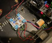
Side note - I cut the traces next to the mounting screws to make sure they stay isolated (for those, like me, who started sweating seeing the screw head next to those vias 🙂)
I made this little guy on perfboard last week. Amazing the kind of clarity and quiet you can get with a couple of resistors and a little Toshiba magic. Using with an Ultrabib, which makes for a nice combo.
My favorite way to control volume in my setup.
Hi All. I have a 10klog stepped attenuator: is thatt value too low for Rev2 instead of 20k?
Thanks
Thanks
Peppennino - As ZM says, the B1 is indifferent to the value of the potentiometer. If you have any sources with an unbuffered tube output, then maybe try to get a higher value potentiometer, but if all your sources are transistor output, the 10K will work beautifully.
Many thanks to both. I have a buffered solid state dac and I'm building an 834PT which has a cathode follower output. May this preamp cause problems?
Going up to dual 15V supply would be a problem? I'm considering to add a mini-Pearl in the same cabinet and share the PSU...
Thanks
Thanks

- Home
- Amplifiers
- Pass Labs
- B1 Rev. 2