Another thing to think about is that the feel of the rotary switch will be effected greatly by the diameter of the knob... the force required will be much reduced, and the feel much lighter if you use a really big knob.
Maybe buying one of these and putting B1 circuit inside would be good idea for fast project 🙂
Passive Preamp Preamplifier 48 Stepped Attenuator Highend for Audiophiles | eBay
Though I have no idea about it's quality, just seen it on eBay looking how the cheap chinese stepped attenuators look
Passive Preamp Preamplifier 48 Stepped Attenuator Highend for Audiophiles | eBay
Though I have no idea about it's quality, just seen it on eBay looking how the cheap chinese stepped attenuators look
Earlier I had a problem using LDR with B1,now switched to TE 47k dual pot 27ESB473MMF50NF - TE CONNECTIVITY / CITEC - POTENTIOMETER, D/GANG LOG 47K | element14 India
It sounds great.
Regards,
Sachin
It sounds great.
Regards,
Sachin
I don't expect that it will sound the same, but that doesn't mean you shouldn't
build it and see.
😎
build it and see.
😎
Thanks for all your cooments.
Zygibajt, the link for the passive preamp you provide is for the product build in Warszawa, Poland: akustyk.com.
The switches are made as custom and the guys making them told that switches configured only for shunt toplogy. They do not make them as series or ladder. They also sell switches you see in that box. Switches named: Khozmo. Khozmo Volume Attenuator
Again only shunt reg.
I don't expect that it will sound the same, but that doesn't mean you shouldn't
build it and see.
😎
Hello
If it sound as good as the original B1, I will be happy.
Thank
Bye
Gaetan
Thanks for all your cooments.
Zygibajt, the link for the passive preamp you provide is for the product build in Warszawa, Poland: akustyk.com.
The switches are made as custom and the guys making them told that switches configured only for shunt toplogy. They do not make them as series or ladder. They also sell switches you see in that box. Switches named: Khozmo. Khozmo Volume Attenuator
Again only shunt reg.
Big sorry, I truly haven't even noticed they are from my country. I have never heard of them and this is first time I see this product and the switches they make. To be hones I'm very rarely interested what is happening in audio inside my country but rather worldwide. Not much happening over here. Thanks for pointing this.
Well, you might be surprosed that some other good staff in electronics world is being made in Poland.
Hello
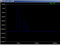
I have simulated, with Ltspice, at 1khz with 1 volt input, the B1 with gain circuit in the post #664
The thd fft spectrum show much more distortions than the original B1 circuit simulation.
Is it normal, what modifications could be done to lower the distortions of the B1 with gain circuit ?
I include an image of the thd fft spectrum and the .asc file of the B1 with gain circuit.
Thank you
Bye
Gaetan
Attachments
Last edited:
Hi Gaetan, note that I have no idea what I'm doing but try increasing R9 to 20K and R10 to 5.6K I think you should see a big improvement in your distortion 🙂
Note I modified the circuit on the B1 side to be closer to the original, but that had very little effect (if any) on the distortion, so I turned to the gain stage. That dropped the THD from 0.17% to 0.05%
Attached is from your original circuit with only the two mentioned resistors changed.
fourier output for modification below:
Fourier components of V(out)
DC component:-0.00144491
Harmonic Frequency Fourier Normalized Phase Normalized
Number [Hz] Component Component [degree] Phase [deg]
1 1.000e+03 3.428e+00 1.000e+00 179.76° 0.00°
2 2.000e+03 1.740e-03 5.076e-04 77.96° -101.80°
3 3.000e+03 1.565e-04 4.567e-05 -145.84° -325.60°
4 4.000e+03 1.255e-05 3.660e-06 -124.45° -304.21°
5 5.000e+03 1.556e-06 4.539e-07 50.03° -129.73°
6 6.000e+03 1.332e-07 3.884e-08 44.86° -134.90°
7 7.000e+03 4.876e-08 1.422e-08 -153.42° -333.18°
8 8.000e+03 3.334e-08 9.726e-09 177.73° -2.04°
9 9.000e+03 2.812e-08 8.203e-09 171.55° -8.21°
Total Harmonic Distortion: 0.050964%
Date: Fri Feb 08 23:31:43 2013
fourier output for unmodified output below:
Fourier components of V(out)
DC component:-0.00535448
Harmonic Frequency Fourier Normalized Phase Normalized
Number [Hz] Component Component [degree] Phase [deg]
1 1.000e+03 3.299e+00 1.000e+00 179.97° 0.00°
2 2.000e+03 5.639e-03 1.709e-03 89.41° -90.56°
3 3.000e+03 4.213e-04 1.277e-04 -178.57° -358.54°
4 4.000e+03 3.495e-05 1.059e-05 -91.62° -271.59°
5 5.000e+03 3.108e-06 9.421e-07 2.08° -177.89°
6 6.000e+03 3.431e-07 1.040e-07 110.15° -69.82°
7 7.000e+03 1.465e-07 4.439e-08 -177.64° -357.61°
8 8.000e+03 1.041e-07 3.155e-08 -179.89° -359.85°
9 9.000e+03 8.890e-08 2.694e-08 176.92° -3.05°
Total Harmonic Distortion: 0.171381%
Tony.
Attachments
Hello wintermute
I'm surprise, I have simulated your suggestion and despite that the input Jfet do receive only 669 micro amp of DS current, the thd are lower !!
Any explanation about it ?
Thank you
Bye
Gaetan
I'm surprise, I have simulated your suggestion and despite that the input Jfet do receive only 669 micro amp of DS current, the thd are lower !!
Any explanation about it ?
Thank you
Bye
Gaetan
Last edited:
Hi Gaetan, As I said I have no Idea what I am doing, so any explanation will be speculation on my part... I tried isolating the gain stage from the buffer stage, in case it was an interaction between the two cricuits but it didn't change things, so it appears that the distortion is directly related to the amount of current flowing through the fet (I also simmed with 10K and 2.8K first and it was higher in distortion).
Although the gain stage is about as simple as it gets, I unfortunately do not really know enough to say how and why things affect the distortion, I just had a hunch that increasing the resistance may help.
Tony.
Although the gain stage is about as simple as it gets, I unfortunately do not really know enough to say how and why things affect the distortion, I just had a hunch that increasing the resistance may help.
Tony.
Can anyone help me wire this to my BI please ? thank you , Rich
44D30-01-2-AJN Grayhill Inc | GH4402-ND | DigiKey
44D30-01-2-AJN Grayhill Inc | GH4402-ND | DigiKey
Cheers Bass ,
I want to use it for input selector ..... 3 inputs ?
numbers 1 to 12 on the back .... how do I figure out which is + and - ?
I guess the pins closer to the chassis are the output to L1 and R1 ?
thank you , Rich
I want to use it for input selector ..... 3 inputs ?
numbers 1 to 12 on the back .... how do I figure out which is + and - ?
I guess the pins closer to the chassis are the output to L1 and R1 ?
thank you , Rich
I would start by planning to insert it in place of the input 2 on the B1 board... I'm assuming you're using Pass boards. I find that the signal path traces for the input 2 are a tiny bit more direct... probably makes no difference but...
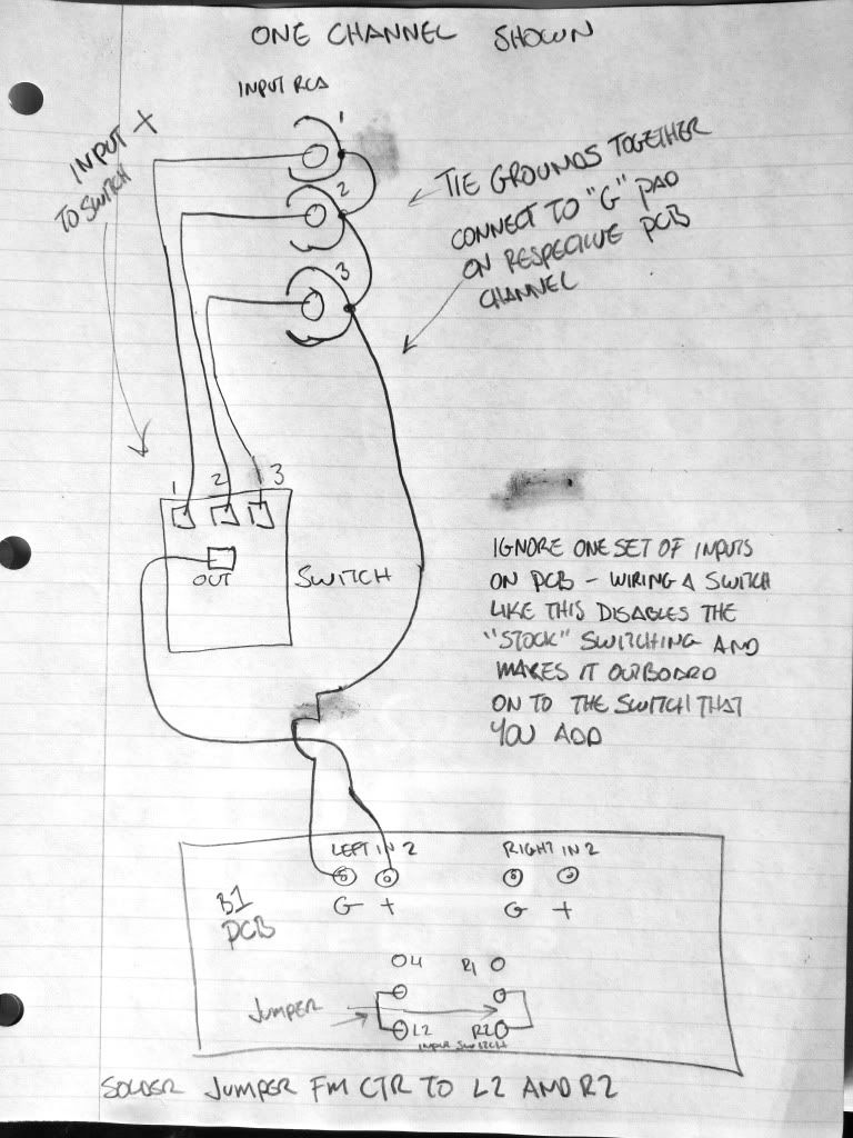
Of course you could still use the board supplied traces for two inputs and using your switch and another single switch wind up with 4 total. Tie the grounds (all the inputs on the board share the common ground) and use the switch to select 1 of 3 pair hot leads!
30°f and dark in Minnesota
Of course you could still use the board supplied traces for two inputs and using your switch and another single switch wind up with 4 total. Tie the grounds (all the inputs on the board share the common ground) and use the switch to select 1 of 3 pair hot leads!
30°f and dark in Minnesota
Last edited:
You will have to use your DMM and ring out the connections in the various switch positions to determine which pins are the switched inputs and which are the outputs. Once you have that done, then connect via this sketch -
I think I have a problem with the selector .... can't get any continuity with the DMM .
Can I use this instead ? 7203L1YZQE C&K Components | CKN1150-ND | DigiKey
I need only 2 inputs for DAC and Phono .
Rich
Can I use this instead ? 7203L1YZQE C&K Components | CKN1150-ND | DigiKey
I need only 2 inputs for DAC and Phono .
Rich
That will do nicely Rich its how I did my DCB1.Don't forget to cross over the wires so to speak so that the input corresponds to the switch position.
There is also a nice one from Farnell
5646A9 - APEM - SWITCH, DPDT | Farnell United Kingdom
There is also a nice one from Farnell
5646A9 - APEM - SWITCH, DPDT | Farnell United Kingdom
- Status
- Not open for further replies.
- Home
- Amplifiers
- Pass Labs
- B1 builders thread