Hi tinitus,
There is a minor problem with your buffer, the lack of gate bias to the top JFET.
There are three things you can do to fix it.
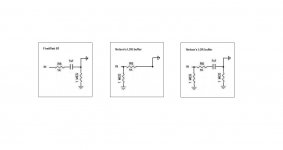
1. Fit a link in place of the 1uF cap.
2. Fit a 1M ohm resistor between the gate and ground.
3. Move the cap to the input pin, then add a 1M ohm resistor between the free end of the cap (the new input pin) and ground, this option would also protect the LDR from DC.
There is a minor problem with your buffer, the lack of gate bias to the top JFET.
There are three things you can do to fix it.
1. Fit a link in place of the 1uF cap.
2. Fit a 1M ohm resistor between the gate and ground.
3. Move the cap to the input pin, then add a 1M ohm resistor between the free end of the cap (the new input pin) and ground, this option would also protect the LDR from DC.
I also wonder about the TL431 reg
been looking at spec sheets, Texas especially
but thiose are shunt regs, connected to ground
is this configured as a constant current source/sink ?
been looking at spec sheets, Texas especially
but thiose are shunt regs, connected to ground
is this configured as a constant current source/sink ?
great 🙂
thanks for checking
btw, would this look better ?
That works ok too.
or per your 1. suggestion, remove cap
looking more like Nelson's schematic
well, I sure don't hope modern source like CD etc puts out dc
so there may be no need for a cap before buffer, I guess
I would put the cap at the input, job done.
I also wonder about the TL431 reg
been looking at spec sheets, Texas especially
but thiose are shunt regs, connected to ground
is this configured as a constant current source/sink ?
No, its just a fancy adjustable zenner diode.
most if not all DACs output an offset voltage.
Could that leak through to the input of a receiver?
Could a faulty output stage of a source send offset to a receiver?
Keep the DC blocking cap.
Keep the 1k0 before the 1M0. Then add an RF attenuator across the 1M0.
There is no disadvantage to adding a 200r gate stopper to the jFET.
Could that leak through to the input of a receiver?
Could a faulty output stage of a source send offset to a receiver?
Keep the DC blocking cap.
Keep the 1k0 before the 1M0. Then add an RF attenuator across the 1M0.
There is no disadvantage to adding a 200r gate stopper to the jFET.
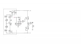
cual es el esquema de este preamp. de antemano gracias y perdon ~ which is the format for this preamp. in advance thanks and forgiveness
English please.
dave

Keep the 1k0 before the 1M0.
Then add an RF attenuator across the 1M0.
There is no disadvantage to adding a 200r gate stopper to the jFET.
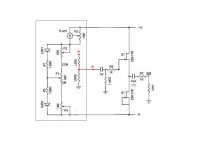
like this ?
what is meant by before/after is not always obvious 😕
RF attenuator ?
Attachments
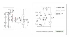
I can't get out my head asking why Nelson placed those components like he did
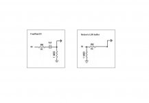
I mean, why is the LDR buffer shown totally opposite the B1
I like to think there must be a reason to not just do it the 'B1 way'
but why ?
attachments show the B1 and LDR buffer
I mean, why is the LDR buffer shown totally opposite the B1
I like to think there must be a reason to not just do it the 'B1 way'
but why ?
attachments show the B1 and LDR buffer
Attachments
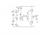
ehh, not to forget the 1meg ohm resistor mounted on input RCA to ground
is that what it is, a variation shown with the first 1meg mounted on LDR shunt resistor
is that what it is, a variation shown with the first 1meg mounted on LDR shunt resistor
cap is added without changing anything on the original schematic by Nelson
I like that one, thanks
regarding 1meg reistor on input RCA
I wonder why use a grounding resitor on each input RCA
instead of just one 1meg placed after input selector
is it to drain any possible noise from each source ground still connected
but when using a 4-pole selector switching off both signal and ground,
I reckon it will then be ok with just a single 1meg ground resistor mounted on selector
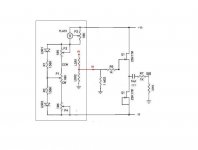
Hi tinitus,
The drawing is a little messy, but this is the permutation you want.
ehh, with cap before the LDR 'resistor', will it not see a varying load, and thus change low cut off when attenuation changes 😕
but may be a small cost for a simpler curcuit

regarding 1meg reistor on input RCA
I wonder why use a grounding resitor on each input RCA
instead of just one 1meg placed after input selector
I would need to see the complete circuit to comment.
is it to drain any possible noise from each source ground still connected
but when using a 4-pole selector switching off both signal and ground,
I reckon it will then be ok with just a single 1meg ground resistor mounted on selector
It's standard practice, with unknown equipment, the previous stage may have an output cap without terminating resistor - two capacitors in series without a grounding resistor is not a good idea.
ehh, with cap before the LDR 'resistor', will it not see a varying load, and thus change low cut off when attenuation changes 😕
As the top LDR decreases in value, the bottom one increases - the impedance will vary a bit, but overall should remain fairly constant.
It's standard practice, with unknown equipment, the previous stage may have an output cap without terminating resistor - two capacitors in series without a grounding resistor is not a good idea.
As the top LDR decreases in value, the bottom one increases - the impedance will vary a bit, but overall should remain fairly constant.
🙂
- Home
- Amplifiers
- Pass Labs
- B1 Buffer Preamp