For the B1 could you also use a modified version of the Pearl psu to power it? For as far as i can understand the psu you have to modify/change the resistors around the 2 ZTX450 and the IRF9610, and not only lower the input voltage, but what should the values become to get 18v out of the psu, could anyone help me with that??
Attachments

cHoc said:
... what should the values become to get 18v out of the psu ... ??
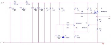
First off, I recommend D1 of 9.1V Zener, and R12 is to be lowered to 10K from 22K. Then it will give us 18V output.
Cheers,
>>🙂<<
cHoc said:For the B1 could you also use a modified version of the Pearl psu to power it? For as far as i can understand the psu you have to modify/change the resistors around the 2 ZTX450 and the IRF9610, and not only lower the input voltage, but what should the values become to get 18v out of the psu, could anyone help me with that??
Babowana said:
First off, I recommend D1 of 9.1V Zener, and R12 is to be lowered to 10K from 22K. Then it will give us 18V output.
Cheers,
>>🙂<<
🙄
from where is current for D4 comming ?
Zen Mod said:
🙄
from where is current for D4 comming ?
From the rail and through an "additional resistor" (it is missing now) to the zener. The size of resistor is to be considered based on the zener current.
Why don't you just add the resistor and correct us at the first place?
Naughty boy . . .

Cheers,
>>🙂<<
Zen Mod said:
🙄
from where is current for D4 comming ?
You're right, Zen mod, i forgot one resistor, it is in this scematic added, and the value of R12 is changed to 10k
Attachments
thanh1973,
Here is the B1 model I did for LTSpice. It's is simplified a bit from your's, but you should be able to use this to compare differences. Like you I have set the 25k input pot set to half. Simulating the transient, I get the 2nd harmonic at -85dB, 3rd at -120dB and 4th at -150dB and no higher harmonics. The AC Analysis shows that the bandwidth goes up to an F3 of about 3 MHz.
Hopefully you can work out your problem from this.
Jim
Attachments
Thanks you fixed the problem.
I went through each directive starting with the one on top in your circuit, and added an extra directive after each run. It wasn't until .plotwinsize=0 was added that it worked.
I went through each directive starting with the one on top in your circuit, and added an extra directive after each run. It wasn't until .plotwinsize=0 was added that it worked.
BFNY said:Here's a revision with 1M input resistor (no pot)
To be clear, the second version is a "universal" version correct?
Omit the 1M resistor and you can use a pot in front of the B1, put in the 1M resistor and you can use it as a straight buffer before another device.
With Mr. Pass' ***PERMISSION*** would you be offering these? 😀
It seems the B1 PCB's on the PassDIY site evaporate faster than beer at a frat party...

(the hope is to have OFFICIAL B1 PCB's approved by Mr. Nelson available)
thanh1973 said:If you want a genuine pcb all you have to do is place an order.
As per the site...
"Already sold out. More on order. Check this space."
http://www.passdiy.com/order.htm
troystg said:
To be clear, the second version is a "universal" version correct?
Omit the 1M resistor and you can use a pot in front of the B1, put in the 1M resistor and you can use it as a straight buffer before another device.
With Mr. Pass' ***PERMISSION*** would you be offering these? 😀
It seems the B1 PCB's on the PassDIY site evaporate faster than beer at a frat party...
(the hope is to have OFFICIAL B1 PCB's approved by Mr. Nelson available)
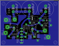
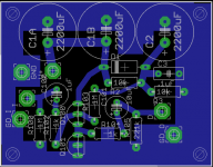
You are right, the 1M resistor (or it can be smaller) gives you a standalone mono buffer. Note there some other differences - the PS caps are smaller, and per channel, as is the gate bias scheme. Also the position of the 1K resistor and coupling cap are switched. The 1 ohm power supply resistor is off board, used between the board and the +18V supply. So it's not an "official" B1 circuit per se.
I did this because I needed a buffer between the mono composite output of older solid state/tube tuners and a stereo MPX board (input impedance 40K). Many of these old tube tuners have fairly high output impedance and work best against 1M, not 40K. It needed to be compact to fit inside the case of old tuners.
I may also use it on the output of the stereo MPX adapter in the filter section, where I now use op-amps...if it sounds a better, which I expect it will.
If you want the official B1 version, buy it from First Watt.
Since they offer the Gerber files, it would also be fairly easy, with approval, for someone to get a group buy going to make a large quantity of official B1 boards.
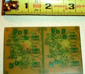
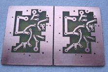
I just thought people would be interested in seeing how small you can get this buffer circuit on a board. I'll post pics of the stuffed version in a few days. I made the board at home last night using the toner transfer method. For me, it works well for small qty.
Bob
Hi Troystq
If you wait you will never get one.
What you have to do is place an order. I placed an order and received mine over a month ago now even though the website said they were still sold out.
So if you want a genuine one place an order and you should have it within 2 to 4 weeks.
If you wait you will never get one.
What you have to do is place an order. I placed an order and received mine over a month ago now even though the website said they were still sold out.
So if you want a genuine one place an order and you should have it within 2 to 4 weeks.
- Home
- Amplifiers
- Pass Labs
- B1 Buffer Preamp