getting started on my B1
It's Christmas out my house! My postal service promptly delivered my parts from DigiKey and I'm ready to get started.
My version is based off of Salas' design, but as he advised, one can add bells and whistles to Papa's B1.
1) 317/337 regulators for each channel. I can adjust the voltage for each channel independently to correct for DC offset.
2) Panasonic TK-1 relays (5 v) to handle up to 3 inputs - cd, phono, and aux. These came from a switch box I dreamed up..recycled parts.
3)2 Panasonic DS2Y relays for the output, one for left channel, one for
right channel to give me 2 outputs - one to my Adcom, one to my Alesis Masterlink for recording to digital
4) because I am a neurotic newbie, I decided to power the relays from a separate small Tamura xformer using voltage regulators (7805/7812) and not from the xformer powering the Jfets
5) l like Papa's use of separate pots for left and right..so that's what going into the box
6) I found a thread that KOA Speers can replace Kiwames...so be it..I've got mine from Mouser
I bit the bullet and bought LSK170s from the group buy and also the 2n5459 Fairchild Semi jfet. All my jfets are now matched and ready to go.
My game plan is to wire up the B1 and use the 2n5459 first. Once it is broken in, I am going to record some of my vinyl to the Masterlink..in 24/96 of course!
Then remove the 2n5459s and replace them with the LSK170s. Repeat the same procedure and then listen between both sets of recordings to determine if I can hear any difference.
I'll be wiring P2P and have the components laid out using ExpressPCB software, so stuffing the vectorboard will go more quickly, as well as the wiring.
I'lll probably have a few questions on wiring, since I have a bit of silver wire laying around and other types of hookup wire. I want to minimize screwups because of a bad wiring choice on my part.
Photos will follow later.
Ground wiring question re. B1
One issue that I have always had trouble wrapping around my brain cells and that is correct grounding in P2P. In some of the forums, the comment is that star grounding is not necessary or benefits are nonexistent. When I viewed the B1 pcbs from Papa, and the schematic, signal and power share the same ground.
So here are my thoughts and please let me know if I'm about to build the world's best oscillator or smoke generator instead of a nice version of the B1 sans coupling caps:
Run 18 gauge solid core around the board and tie resistors, decoupling caps, ground inputs and outputs, regulators, etc. to this ground wire. V+ and V+ will be distributed using 20/22 gauge solid core and signal inputs/outputs will be wired using 24 gauge silver solid core wire.
Does this make sense in a p2p preamp design?😕
Thanks
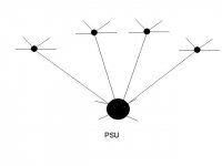
Do sub stars. Create local star nodes for each block. Then tie tails from each one to a single point meeting the PSUs star node.
single sided B1 layout file
in the spirit of sharing, a layout file for a single sided version of the B1 is attached so that others may use or modify, including turning off component outline and text layer. Images of the layout were posted previously on October 27.
This was drawn in PCB Artist, which is a free download from www.4pcb.com)
Regards, Joe
Attachments
Re: getting started on my B1
 Pete Millett, among many others, say they can't hear a difference between the Kiwames sold at partsconnexion and the KOA Speers from Mouser
more like KOA Speers ARE 'Kiwames'...have you seen both side by side?sonidos said:6) I found a thread that KOA Speers can replace Kiwames...so be it..I've got mine from Mouser
Pete Millett, among many others, say they can't hear a difference between the Kiwames sold at partsconnexion and the KOA Speers from MouserWhich KOA Speers?
Hi, which type of KOA Speers resistor sounds like Kiwame? is it MF or CF or something else. I searched for info here and Google but found nothing re the sonic properties, do you have a link to the thread you saw.
Thanks RC
Hi, which type of KOA Speers resistor sounds like Kiwame? is it MF or CF or something else. I searched for info here and Google but found nothing re the sonic properties, do you have a link to the thread you saw.
Thanks RC
Re: Which KOA Speers?
I googled today and most probably is the SPR series..... somebody colud confirm?
http://www.koaspeer.com/pdfs/res47.pdf
calvert73 said:Hi, which type of KOA Speers resistor sounds like Kiwame? is it MF or CF or something else. I searched for info here and Google but found nothing re the sonic properties, do you have a link to the thread you saw.
Thanks RC
I googled today and most probably is the SPR series..... somebody colud confirm?
http://www.koaspeer.com/pdfs/res47.pdf
KOA Speer
www.mouser.com
Mouser part#s
660-SPR1CT52R331J
660-SPR2LT521R102J
Note the SPR in the part#.
For me, if it comes off the same assembly line in the same factory and looks the same...and the fact that us DIYers buy in such small quantities that a manufacturer isn't going to retool for small runs...then it's the very same resistor. I don't have any proof of that...just sayin'.. 😀
If I get a chance, I'll post photos of the KOA version and Salas already has posted pics on his B1 with Kiwames for you to compare.
My life is hectic right now with my wife about ready to deliver and her renewal of her immigration status coming up in a few weeks.

Choky,
I made sure that the parts arrived after the baby shower at our home. My wife asked me to paint some areas of our home and clean out the garden of weeds. I don't know how I could have explained needing time to work on the B1.😀
Fortunately, she knows I need some diy time each night. We'll put that to the test in a few weeks when she delivers.
Anyone know what the 2 connections are above and to the right of DIY B1 R0 on the PCB? Are these test points?
sonidos said:Fortunately, she knows I need some diy time each night. We'll put that to the test in a few weeks when she delivers. [/B]
Dont worry about the wife. Try explaining it to the new bald headed boss 🙂
Congratulations!
Ri
dviswa said:
Bob,
Thanks a lot. I downloaded the program and as you said the program only seem to compute 2 pole filters instead of 3 pole filters. This will be a great start.
Thanks again,
Dinesh
I was playing around and found out you can make it calculate 3 pole filters. Go to options, and click on "use 3 pole section".
 Duh!
Duh!Sorry I didn't see it earlier. This makes it a great software tool to make 3 pole active filters based on the b1 buffer.
Bob
Can you guys critique my layout?
Feel free to use it if you like it.
I was going to wait and buy the boards, but the buzz in my P2P is driving me crazy.
Thanks
Uriah
edit:
C101, C201 and R1 are all on the opposite side as the rest of the components. All inputs/outputs are wires. Power comes in opposite end of board as other inputs/outputs. C3 will be connected to legs of C2.
There is only one set of inputs. I will make a separate board for multiple inputs that will be switched and send only source signal at a time to the B1.
Attachments
Actually, feel free to use it, but I can post black and white without the silkscreen so that you can use that for etching after I get some feedback.
Uriah
Uriah
Should add that all traces are 1.27mm with .5mm between traces and ground plane. Ground plane covers entire board.
Question: Why is R1 3W? Doesnt make sense to me.
Uriah
Question: Why is R1 3W? Doesnt make sense to me.
Uriah
Just some basic protection on the power input I think
a 3 watt resistor should be able to survive a continuous short circuit condition on the board without smoke.
using a typical wall power supply with around one amp rating, it could get very hot if shorted.
power resistors should be mounted up off the board at least 3mm to reduce possibility for damage due to heat
- Home
- Amplifiers
- Pass Labs
- B1 Buffer Preamp