AndrewT said:this does not seem right.
Are you biasing the amplifying jFET at above it's Idss? Does the sim allow this?
Ooopppss , nope that was my poor writing....
lower jfet 11mA Idss , drive jfet 9mA Idss = 0.00090%
drive jfet 11mA Idss , lower jfet 9mA Idss = 0.00115%
Don't understand why or how.. these are real measurements, no sims
Re: just for fun ? COTTAGE
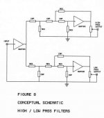
1984. The drawings were done on one of the first MacIntoshes
shipped in California.
Zen Mod said:ya see - old Papa's work .......
1984. The drawings were done on one of the first MacIntoshes
shipped in California.
Re: Re: just for fun ? COTTAGE
I believe ;
but - most interesting drawings seems weren't made with Macs 😉
Nelson Pass said:
1984. The drawings were done on one of the first MacIntoshes
shipped in California.
I believe ;
but - most interesting drawings seems weren't made with Macs 😉
Input Impedence
No pointers for a newbie? :-(
I was wondering if a low input impedance that I'd potentially get from using a shunt-type stepped attenuator would be much of a problem. My source currently has an output impedance of 50 ohms. The effects I'd notice if input impedance went too low would be just more noise, is that right? Would it be enough to defeat the purpose of having such a low-noise circuit?
I was also wondering - would a log-taper pot or attenuator be suitable in place of the linear pot used in the article?
thanks,
-d
Are you asking if a low impedance source seen by a buffer would
be a problem? Not if you retain the input resistor on the Gate that
you see in the schematic.
be a problem? Not if you retain the input resistor on the Gate that
you see in the schematic.
Input Impedence
I meant if I used this shunt-type of attenuator, the input impedance of the buffer would vary with the volume I set it to, so the input impedance would range from 2K to 50K (or whatever I decide to solder on to it).
So I was wondering if I'd start to see some adverse effects when the input impedance is so low...
I think what you have found confirms something that John Curl said about applying a high gate voltage to the jFET to force it to pass more current.tschrama said:.....lower jfet 11mA Idss , drive jfet 9mA Idss = 0.00090%
drive jfet 11mA Idss , lower jfet 9mA Idss = 0.00115%
Don't understand why or how.. these are real measurements, no sims
Is there a problem doing this when the signal level rises?
What happens when the input signal cancels the gate bias voltage and the upper FET is no longer loaded by the CCS?
When the upper FET is already at slightly positive Vgs -- which happens when its Idss is lower -- it might happen its gate diode gets significantly forward biased when there is enough positive output current. Maybe (just a vague guess) this forward biasing is reponsible for the seen decrease in THD... gm increases with Id so the ouput would be a bit too high with increasing currents and the positive gate current would cancel that effect partly by reducing Vgs a little... but this would be rather sensitive to many things, like drive impedance etc.Originally posted by AndrewT
Is there a problem doing this when the signal level rises?
- Klaus
Re: Input Impedence
It's in fact the opposite. Assuming you are talking of source impedance in parallel with attenuator.
Diomedian said:The effects I'd notice if input impedance went too low would be just more noise, is that right?
It's in fact the opposite. Assuming you are talking of source impedance in parallel with attenuator.
Re: Re: Input Impedence
Alrighty - either I'm asking the wrong questions, or the questions don't make any sense, or my assumptions are wrong, or... some combination. 🙂 Please treat me like I don't know anything, because this is a reasonable approximation of actual knowledge.
1) It is desirable for the buffer to have high input impedance? This makes it easier for the source to drive - yes?
2) The input impedance of the B1 is determined solely by the pot? This is because the source sees only a 25K resistor (the whole length of the pot)?
3) On the B1 side of the pot, it sees a 1K in series with a variable resistance (some part of the pot), and a variable resistance to ground (the rest of the pot) paralleled with output impedance of the source?
4) If I replace the pot with a 2K resistor, (that is to say the circuit now looks like input -> 1K -> 1uF -> 2sk170, and input -> 2K -> ground), the input impedance of the B1 is now 2K, is that correct?
5) Doing as in question 4) - this is the equivalent of a shunt-type attenutator set to min volume (assuming 2K is the smallest value used by the attenuator)? Er... or is that max volume?
6) Would a ladder-type attenuator be a better idea for this circuit since the shunt-type gives such a low input impedance?
7) Finally, is there a reason a linear taper pot was used, and not a log scale? Was it simply cheaper, or does this circuit for some reason require a linear pot?
Or... should I just stop asking all these silly (and possibly terribly insignficant) questions and just go test it for myself? hehe
Thanks in advance, and sorry for all the noise on this thread...
-d
analog_sa said:
It's in fact the opposite. Assuming you are talking of source impedance in parallel with attenuator.
Alrighty - either I'm asking the wrong questions, or the questions don't make any sense, or my assumptions are wrong, or... some combination. 🙂 Please treat me like I don't know anything, because this is a reasonable approximation of actual knowledge.
1) It is desirable for the buffer to have high input impedance? This makes it easier for the source to drive - yes?
2) The input impedance of the B1 is determined solely by the pot? This is because the source sees only a 25K resistor (the whole length of the pot)?
3) On the B1 side of the pot, it sees a 1K in series with a variable resistance (some part of the pot), and a variable resistance to ground (the rest of the pot) paralleled with output impedance of the source?
4) If I replace the pot with a 2K resistor, (that is to say the circuit now looks like input -> 1K -> 1uF -> 2sk170, and input -> 2K -> ground), the input impedance of the B1 is now 2K, is that correct?
5) Doing as in question 4) - this is the equivalent of a shunt-type attenutator set to min volume (assuming 2K is the smallest value used by the attenuator)? Er... or is that max volume?
6) Would a ladder-type attenuator be a better idea for this circuit since the shunt-type gives such a low input impedance?
7) Finally, is there a reason a linear taper pot was used, and not a log scale? Was it simply cheaper, or does this circuit for some reason require a linear pot?
Or... should I just stop asking all these silly (and possibly terribly insignficant) questions and just go test it for myself? hehe
Thanks in advance, and sorry for all the noise on this thread...
-d
1. Yes.
2. 25k in parallel with 1M. Still 25k.
3. Yes.
3. Yes
4. No. There is also a resistor in series with the input which generally determines the worst case scenario as seen from the source
5. As in 4. Max volume is determined by series resitor and max value of shunt; if shunt is open circuit there is no attenuation. If shunt is a pot attenuation is set between pot value and series resistor. Min volume is set at min value of shunt (0 ohm)
6. ???
7. Log pot would work just as well
Your questions are not silly. If you want to see silly i can point you to a few threads to compare 🙂
Do you intend using a rotary switch or a pot for the shunt? If using a pot you are likely to lose some voltage gain at max setting across the shunt. You can calculate this depending upon the resitor values and see if it's acceptable. Most people use shunt controls as a good compromise between quality and cost - a really nice series resistor and a cheap pot sounds significantly better than a cheap pot on its own.
I think the "ladder" and "log" are the same, no? This is were a series of relays is used so that they are not in the chain.
khundude said:I think the "ladder" and "log" are the same, no? This is were a series of relays is used so that they are not in the chain.
No, it's not the same, it's not even something you can directly compare.
"Ladder type attenuator" refers to topology, to way how the attenuator is built, ladder-like.
"Log" refers to attenuation characteristic, it represents mathematical function of change of resistance from potentiometer's/attenuator's wiper to ground and number of degrees when you turn the knob.
Example:
a) We have 10k log. potentiometer/attenuator . We turn the knob to 12 o'clock position. Resistance from wiper to ground is 500 Ohms.
b) We have 10k linear potentiometer/attenuator . We turn the knob to 12 o'clock position. Resistance from wiper to ground is 5k.
Oh boy, I wish I could put it clearly in less words

analog_sa said:
6. ???
Do you intend using a rotary switch or a pot for the shunt?
Thanks for all the replies analog_sa!
To rephrase #6, I was thinking that since using a shunt-type attenuator causes input impedance of the buffer to vary with the volume setting, would it be better to use a ladder-type attenuator (not in shunt mode) that doesn't cause the input impedance to vary?
If I use a shunt at all, it would be with an attenutator.
thanks again,
-d
Should I expect higher noise and THD figures, if I use LM 317 regulator with CRC filter for PSU instead of discrete one?🙄
supernet said:Should I expect higher noise and THD figures, if I use LM 317 regulator with CRC filter for PSU instead of discrete one?🙄
use stacked 317s , with both heavy bleed and mucho uFs on output
( in that case with all necessary diodes for chip protection)
Zen Mod said:
use stacked 317s , with both heavy bleed and mucho uFs on output
( in that case with all necessary diodes for chip protection)
OK.
I will use two separate regulators for each channel. I was thinking to use 2X4700 uF 35 V before LM 317 and 100 uF at the outout. For the buffer, I will probably use two 4700 uF caps / mono channel instead od 15000 uF.
Should this be OK?
supernet said:
OK.
I will use two separate regulators for each channel. I was thinking to use 2X4700 uF 35 V before LM 317 and 100 uF at the outout. For the buffer, I will probably use two 4700 uF caps / mono channel instead od 15000 uF.
Should this be OK?
when I wrote stacked , I meant as in attached schm . - cascaded 317 , with ref leg of input one connected to output , not to ground ;
that way input one is prereg for second 317.
heavy bleed - I meant - put resistor load on output of reg
in fact - you can pretty easily use exact schmtc
Attachments
- Home
- Amplifiers
- Pass Labs
- B1 Buffer Preamp