the British code covers various insulation types and enclosures, behind wall board surrounded by fibre insulation etc.
I don't know the document reference, I'm not an electrician. I'm pretty certain it's not detailed in the 16th edition, is that current, or do we have a 17th edition?
I don't know the document reference, I'm not an electrician. I'm pretty certain it's not detailed in the 16th edition, is that current, or do we have a 17th edition?
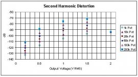
OK here are the rest of the measurements.
1k Pot gives least 2nd harmonic distortion, 200k Pot gives the most second harmonic distortion.
However I really wouldn't recommend anyone using a 1k pot, as this may pose a serious load for a cd player. The measurement was done for curiosity only
1k Pot gives least 2nd harmonic distortion, 200k Pot gives the most second harmonic distortion.
However I really wouldn't recommend anyone using a 1k pot, as this may pose a serious load for a cd player. The measurement was done for curiosity only
Attachments
that fits with classic circuit theory. Lower Rs gives best performance.
I was hoping you would find an optimum near the recommended 25k (Rs<=6k).
I was hoping you would find an optimum near the recommended 25k (Rs<=6k).
These measurements were carried out using LSK170 spice model.
I will repeat these measurements with Toshiba 2SK170 spice model and report back if there are any significant difereing trends or differences.
I will repeat these measurements with Toshiba 2SK170 spice model and report back if there are any significant difereing trends or differences.
Thanh1973,
Thanks for running these tests. I am sure there are a lot of us watching in anticipation.
Uriah
Thanks for running these tests. I am sure there are a lot of us watching in anticipation.
Uriah
Grafting the B1 to a Headphone amp
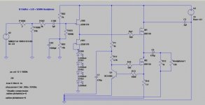
I am planning on grafting a B1 onto the front of a mosfet follower type headphone amp. It has a 24 volt power supply. To be able to directly connect the 2SK170's to the output mosfet, I need to eliminate C101, R104 and R105. To keep the correct bias for the output stage I also need to raise the DC level on the output of the B1 about 6 volts. The plan is to add 4 Red LED's below Q101 and then change the B1 bais resistors R2 to 8K and R3 to 13k. This will also bring the B1 portion back to Nelson's sweet spot of 18V over the jfets. Does this sound reasonable?
Here is the schematic. It's just a work in progress so things like the grounding layout are unfinished.
Thanks
Jim
Attachments
thanh1973 said:These measurements were carried out using LSK170 spice model.
I will repeat these measurements with Toshiba 2SK170 spice model and report back if there are any significant difereing trends or differences.
It will be more interesting to see actual results - so far the models
provided by manufacturers have not given very reliable distortion
sims.
😎
I agree
It would be nice if someone could do real measurements using 10k, 25k, and 50k pots (preferably linear style), in order to get a feel for how the the simulated results compare with real measurements.
I hope at least the simulated results are indicative of the behaviour seen with real measurements.
I have very little confidence in the exact quantitative results of these simulations but would hope the trends and differences are reasonably correct (ie qualitatively ok).
C3 on PassDIY Board
I've been looking at the Gerber files of the B1 board posted at PassDIY with a viewer (as I'm trying to make a layout myself), and it would seem that the board doesn't match the schematic.
In the schematic, C3 parallels C2, but on the board, C3 parallels C1. Does this make any difference? I'm a newb and as such, I'm not too certain as to the purpose of the components in the PS.
thanks,
-j
Tea-Bag said:any problem using a 1N4148 for D1?
Says it's there to draw down current when turned off, so I think think this is fine.
jacco vermeulen said:A 1N4148 is a hirsute 1N914.
I checked it for abnormal hairs, I see none.

The specs looked similiar to me. So I will use it, since I have a few hundred of them.
I am now foraging for proper 1uf caps. Any suggestions would be welcome.
I am considering proto-ing the 10uf's with motor starts, but also thinking about using bipolar e-caps to instigate controversy.
thanh1973 said:I agree
It would be nice if someone could do real measurements using 10k, 25k, and 50k pots (preferably linear style), in order to get a feel for how the the simulated results compare with real measurements.
I'm still looking to do this shortly. To make it easier, I think just inserting resistors in front of the input to increase source resistance would be easier, but I'll use pots on hand as well.
It's harder to rig up pots for short experiements due to the hum and noise in a temporary test. You can't believe how sensitive things get to noise effects in open wiring at -110 to -140 dB. You scratch your head and you see a change!
Zen Mod said:besides fuglyness ..... interesting ...... input cap , output cap , comp. jfet buff as in Papa's Lightspeed , single voltage supply ?
less is more 😀
Choky,
In your modified B1 schematic, you replaced C100, C101, C200 and C201 with what look like trim pots or are those variable resistor values? 220-270 and 150-180
Can I use Papa's pcb and use your substitutions?
marc brown said:
Choky,
In your modified B1 schematic, you replaced C100, C101, C200 and C201 with what look like trim pots or are those variable resistor values? 220-270 and 150-180
Can I use Papa's pcb and use your substitutions?
you mean this one :
220 to 270 ohms - meaning more ohms , less current through jfets ; choose what you have in drawer , or what you prefer 😉 ...... any value between 220 and 270 ohms ;
lower Jfets have in source series string of one resistor (180 ohms ) and one pot (around 150 ohms ) ;
pot is there for offset setting ; set pot in middle , power on , let it cook for a while , set offset .
repeat after some time ...... voilla !
Zen Mod said:
you mean this one :

220 to 270 ohms - meaning more ohms , less current through jfets ; choose what you have in drawer , or what you prefer 😉 ...... any value between 220 and 270 ohms ;
lower Jfets have in source series string of one resistor (180 ohms ) and one pot (around 150 ohms ) ;
pot is there for offset setting ; set pot in middle , power on , let it cook for a while , set offset .
repeat after some time ...... voilla !
That's the one. Thanks choky!
😎
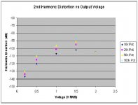
I wasn't going to post these results but since i went to the effort of doing them someone may want to compare them.
These were done using the Toshiba 2sk170 model instead of the lsk170 model.
The trends are the same but the distortion numbers are lower (ie the curves have shifted down)
These were done using the Toshiba 2sk170 model instead of the lsk170 model.
The trends are the same but the distortion numbers are lower (ie the curves have shifted down)
Attachments
do they all coincide (-105dB) at 2Vac input/output?
Now we need a real test @ 2Vac using both the LSK and the 2SK.
Who has the equipment to do that for us?
Now we need a real test @ 2Vac using both the LSK and the 2SK.
Who has the equipment to do that for us?
Purpose of C3
Maybe I should modify my question and then I can decide for myself.
What is the purpose of C3? C1 is a filter, and C2 helps provide half the PS voltage to the gates of C101 and C201 after the voltage divider of R2 and R3, but what about C3?
thanks,
-j
Maybe I should modify my question and then I can decide for myself.
What is the purpose of C3? C1 is a filter, and C2 helps provide half the PS voltage to the gates of C101 and C201 after the voltage divider of R2 and R3, but what about C3?
thanks,
-j
- Home
- Amplifiers
- Pass Labs
- B1 Buffer Preamp