Thanks, I will mail to Pass Labs about the knobs. The box is more than OK, your efforts were wrth it.Papa. From Burning Amp #1.
They are Threshold knobs: (maybe from this?)
Vintage Rare Threshold Model SL10 PreAmplifier for sale - New and Used - PC Game Cheats Codes | PC Cheats Codes
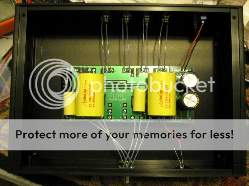
I have a stereo volume pot on the left and the DPDT is actually the knob on the right. Left of center is input one, Center is Off, and Right is input 2.
I only had about .25" around the board on all sides so it's kinda like 10 lbs of stuff in a 5 pound bag in there with the Nichicon KG PS caps folded over the top of everything.
Pics were supposed to be larger. Hope you don't mind if I try again.

Thanks for posting. The construction is very good. Your wiring looks exceptional.
Did you build the chassis? I think the fasteners could be black for a better visual appeal. If you wish, I can offer a good source for them, via PM.
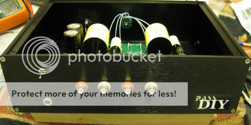
Thanks for the compliment on the build.🙂 I bought the chassis and drilled the holes for connectors, knob and power. I have black screws for it but wanted to see how it would look with contrasting that matched the knob.
I all, I think my first post. I read the whole thread and built the buffer. My first real build since putting together a couple of Hafler kits in the '80s. I'd been using a P1.0 clone and this B1 is amazing. I'm a tad short on volume with a few cds but I think I can live with it because the sound is so transparent.
Thanks to everyone who contributed and a special thanks to Nelson!
Here are a few pics.


Awesome, good craftsmanship!!!
Awesome, good craftsmanship!!!
Thanks! I'm burning in some bypass Russian FT-1s and FT-3s. So far the Thetas with the FTs sounds very nice.
I all, I think my first post. I read the whole thread and built the buffer. My first real build since putting together a couple of Hafler kits in the '80s. I'd been using a P1.0 clone and this B1 is amazing. I'm a tad short on volume with a few cds but I think I can live with it because the sound is so transparent.
Thanks to everyone who contributed and a special thanks to Nelson!
Here are a few pics.
Excellent build Chris. From where did you obtain the chassis?
Regards
Marra
That did'nt work right.😕
Excellent build Chris. From where did you obtain the Chassis?
Regards Keith
Excellent build Chris. From where did you obtain the Chassis?
Regards Keith
Thanks, Keith. The chassis came from Context Engineering. High quality aluminum enclosures designed for maximum flexibility in form and function
Hey Chris,
I had a visitor awhile back, an industrial designer that developed some of the Bel Canto lineup and he chided me on my use of a black toggle on a silver faceplate. I guess I may be getting over-sensitive about mixing black and silver.
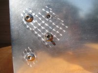
I actually find little to complain about your chassis and the mix of color, the knob looks good in a contrasting color. I spent a good amount of searching to come up with a local supplier of fasteners that has a broad line card of product, including stainless and black oxide in different styles. My oversensitivity even drove me to experiment with engine turning on my last build.
I had a visitor awhile back, an industrial designer that developed some of the Bel Canto lineup and he chided me on my use of a black toggle on a silver faceplate. I guess I may be getting over-sensitive about mixing black and silver.
I actually find little to complain about your chassis and the mix of color, the knob looks good in a contrasting color. I spent a good amount of searching to come up with a local supplier of fasteners that has a broad line card of product, including stainless and black oxide in different styles. My oversensitivity even drove me to experiment with engine turning on my last build.
Attachments
Thanks for the link Chris. Can you give a hint on price please.
$65 natural, $75 anodized plus shipping.
westend,
I'm very visual so I like to experiment a bit...black toggle on a silver panel sounds good to me. I was originally going to do black knob on silver case or black case with silver face and black knob.
I'm very visual so I like to experiment a bit...black toggle on a silver panel sounds good to me. I was originally going to do black knob on silver case or black case with silver face and black knob.
impedance matching for baflle step circuit
I want to use the following (baffle step control) circuit between two B1 buffers:
Baffle Step Compensation
I will use this in a differential setup, so it looks more like this:
Towards a differential active crossover
Rod states that for his circuit:
It is essential that the compensation circuit be driven from a low impedance source, and the load impedance should be reasonably high. There will be little error with loading above 20k, but basically the higher the impedance, the better. Opamp buffers at the input and output may be used if you cannot ensure that the source impedance is 100 ohms or less, and that the load impedance of the following stage is greater than 20k. My recommendation would be to use a buffer stage at the output with an input impedance of about 100k.
Would this be possible with a B1 buffer before and after this circuit?
setting the input impedance of the B1 to >=100k is not a problem.
Setting the output impedance of the B1 may well be a problem.
The standard B1 has ~1050r output impedance, way above the <=100r suggested for your EQ circuit.
The DCB1 substitutes a 220r for the 1k0 to lower the output impedance to ~270r. Still too high.
Pass suggests that the 1k0 can be reduced but at increased stability issues as the resistance is lowered.
He quotes 100r as a likely minimum but adds that stability should be checked. That 100r gives an output impedance ~150r. This is still outside the EQ recommened source impedance.
The B1 can be used as a buffer after to EQ to send the signal on to another receiver.
I would suggest that a different buffer with much lower output impedance be used to drive the EQ.
Most filters are calculated assuming Rs=0r0 and Rload=infinity.
As these source and load impedances close in from the theoretical, the more the filter must be altered to keep the same filtering characteristic. This is not easy. I cannot recall seeing a paper explaining how this can be done. I certainly can't do it, but then I'm still very early in my learning of electronics.
There is one exception that is easy to correct.
When the first section of the EQ is a passive, single pole, low pass filter, i.e. a series resistor (R) followed by a grounding capacitor (C), then it is easy to calculate the new values of the passive components.
The R before the cap assumes Rs=0r0.
If instead you substitute R = R' + Rs, you can find a value for R' that keeps the low pass filter exactly as intended. C remains unchanged and any EQ after this first low pass, sees exactly what theory requires of it.
This is my understanding :
Using a pair of 2SK170s with symmetrical rails and no source degenration, the output impedance of the Single Ended JFET source follower (or if you like, B1) is essentially 1/Yfs, which is about 40R for a 2SK170BL. You can reduce that by either using higher Yfs devices such as 2SK372, or putting more 2SK170s in parallel.
I have being using such buffer circuits to drive filter stages at the output without problems. You just need to make sure the inout impedance is >> 1k. see also Borbely's article.
Patrick
I think N.P.s suggestion regarding the series load R is based on the B1 driving cables of unknown length and other variious unknown capacitive and inductive loads. With a good layout of your circuit all on one PCB, I think the series R can be reduced substantially without stability problems. 
give an opinion on whether the 1k0 output resistor can be reduced to <=50r to meet the RS<=100r condition.With a good layout of your circuit all on one PCB, I think the series R can be reduced substantially without stability problems.
In this site the designer states:
Towards a differential active crossover
I that is true, why can the output impedance of the B1 not be taken into the equation and modify the circuit accordingly?
Towards a differential active crossover
If the desired high-frequency attenuation is Ainf and the baffle step is s, centred at frequency fb, then
2πfbCR1=(1-Ainf)2√(s3)/2Ainf(s-1).
If Ainf=1/3 and s=3dB, then R2=R1 and 2πfbCR1=2.7068.
If we use a valve circuit with output impedance R1=25K and have a baffle step centred at 450Hz, then C=38.3nF, R2=25K and R3=19.6K.
Alternatively, if we use a solid-state circuit where we can get away with lower impedances, we can specify C=100nF and then R1=9.57K, R2=9.57K and R3=7.501K.
I that is true, why can the output impedance of the B1 not be taken into the equation and modify the circuit accordingly?
Hi. I'm thinking about building a B1:
The source would "see" a 10k Ohm pot at the input of the B1, which I would (want to) connect to a pair on Zen V4 with 47,5k in the input and a headphone-amp* at the same time. Is there anything I should be aware of, should I change any resistor-values, capacitor-values, FETs or do you expect this to just work?
Is there a good reason to put a switch (I would probably use relays) in the output and switch between the different amplifiers?
*maybe the "Bijou", maybe something else.
Hello Luda,
the prototype of my preamp/crossover uses a 10K pot at the input without problems. Just make 2 pairs of outputs, one for your Zen and one for your headamp. Why would you put a switch inbetween, you can use them in parallel.
the prototype of my preamp/crossover uses a 10K pot at the input without problems. Just make 2 pairs of outputs, one for your Zen and one for your headamp. Why would you put a switch inbetween, you can use them in parallel.

- Home
- Amplifiers
- Pass Labs
- B1 Buffer Preamp