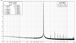
This is with an ADA4625-2 in U2 position. BAL in 4VRMS BAL out 0.5VRMS -18dB. Tried with J6 J7 open/jumpers, couldn't find a difference within the MOTU M4's resolution limit. Same FFT result clamping diodes engaged or not.Measure with/without jumpers, see if there's a difference.
Attachments

0.5Vrms out is low, a better test would be at say 2.5 or 3V out rms (which is closer to the prebias of 4.7V of the diodes).
Jan
Jan
2ViBAL-->4VoBAL jumpers or no jumpers same chart same figures. For this class of sound-cards and settings, secondary details (if there) get masked by their converters performance limits. Even mediocre much older JFET op-amps suffice nearly as good as new gen champions in this case for U2 position.
Attachments
Is that 4v out to the Motu?2ViBAL-->4VoBAL jumpers or no jumpers same chart same figures. For this class of sound-card and settings, secondary details (if there) get masked by their converters performance limits. Even mediocre much older JFET op-amps suffice nearly as good as new gen champions in this case for U2 position.
Correct. 4V RMS from AR's Bal Out to MOTU M4's back panel line-in connected with a balanced TRS lead. To refer more universally than dBFS which is max input signal peak specific, the chart's 0.0058% THD+N translates to 104.73dB SINAD. Consistent with third party reports of ~104dB SINAD ADC performance for the M4.
All the above findings verify George's conclusions. Couldn't put it better into words.Jan's AR is a transparent specs-wise unit.
A great safe, time saver testing tool
George

Not a cheap or quick project but mature and effective. We have to congratulate Jan.

Sadly don't seem able to get upto this voltage in level on my M2, maybe time to look at the M4Correct. 4V RMS from AR's Bal Out to MOTU M4's back panel line-in connected with a balanced TRS lead. To refer more universally than dBFS which is max input signal peak specific, the chart's 0.0058% THD+N translates to 104.73dB SINAD. Consistent with third party reports of ~104dB SINAD ADC performance for the M4.
It's simply double the SE you can have. It was max 2.4V RMS SE if I remember correctly from when I had the M2. They have the same ADC chip (AK5552VN), only difference is that the front combo inputs with the gain control are not direct to the chip and lose THD+N performance in both models vs the extra direct line in at the back found in M4 only.
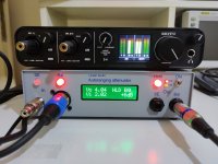
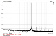
Here's the loop test config. TRS to XLR comes from the M4's back panel Monitor Out goes to AR's Bal In. TRS to TRS from AR's Bal Out to M4's back panel Line In 3. Its four Volt indeed after +6dB gain (I measured 3.996V RMS). ARTA (131kPoints 44.1kHz) reports 0.00047% THD+N. That is -106.55 dB. AKM states -106dB for the AK5552VN. Met spec within experimental error/production tolerances.Sadly don't seem able to get upto this voltage in level on my M2, maybe time to look at the M4
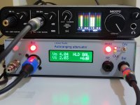
I moved the Bal Out TRS to the M4's IN 2 front combo connector and it accepted 4VRMS. I saw 0.001% or -100dB THD+N this time. You should be able to do so in your M2 as well. They are the same interfaces differing in number of channels and some extra I/O. MOTU states +16dBu max for TRS front inputs on both models. M4's back panel Line In accepts +18dBu that is why the shorter signal bar height on IN 3 picture.
Attachments
Jan hi,
Since there are input coupling capacitors is it safe to connect a DC rail on the AR's inputs to see its AC noise? Like we do on a scope? Or is it likely to be blown due to high energy concerns?
Since there are input coupling capacitors is it safe to connect a DC rail on the AR's inputs to see its AC noise? Like we do on a scope? Or is it likely to be blown due to high energy concerns?
That would be interesting to see! I've tried it with my soundcard equipped with 400V DC input caps and indeed no safety issues but it seems the soundcard does not understand this as signal and the noise is like with input disconnected. Curious to see how AR does.
The noise of modern low-noise power supplies is lower than the noise floor of soundcards. That may be the reason nothing is seen. To properly measure the power supply noise a LNA is required.
True but I was talking about noisy tube psu or even tracing 1kHz signal at tubes' anodes. And it's not that I'm just seeing the soundcard's noise floor, it's more like as if the probe is left disconnected on the air picking all kind of noise although I can see the 1kHz peak. With oscilloscope otoh everything seems clear enough.
What is the part number for the green / white text display?Here's the loop test config. TRS to XLR comes from the M4's back panel Monitor Out goes to AR's Bal In. TRS to TRS from AR's Bal Out to M4's back panel Line In 3. Its four Volt indeed after +6dB gain (I measured 3.996V RMS). ARTA (131kPoints 44.1kHz) reports 0.00047% THD+N. That is -106.55 dB. AKM states -106dB for the AK5552VN. Met spec within experimental error/production tolerances.
I moved the Bal Out TRS to the M4's IN 2 front combo connector and it accepted 4VRMS. I saw 0.001% or -100dB THD+N this time. You should be able to do so in your M2 as well. They are the same interfaces differing in number of channels and some extra I/O. MOTU states +16dBu max for TRS front inputs on both models. M4's back panel Line In accepts +18dBu that is why the shorter signal bar height on IN 3 picture.
So, I built the Auto Ranger that Jan sent me. Now, there is a potential problem in that the requested relays, G6K-2P-DC5, are completely unavailable everywhere with a possible first availability date of 05/22, but for only 250 or so pieces - so no guarantee you will be able to get them to complete the build. I looked on Ebay and the price for this relay is out of the roof - normally, it's basically the cheapest of the G6K series (at Mouser, they're 3.89 each), but whenever a shortage occurs... So I had an idea. I saw from the pictures that the holes on the PCB are quite large, and looking at the datasheet of the relay I could see the difference in spacing with the Y variant is extremely small. The pins are flat and are oriented longitudinally, and this is so because the same package can be used for SMD. So bending the pins outright is extremally difficult to reach the 2.54 spacing needed.
BUT... I twisted the pins so the flat end is transversal in respect to the body orientation, allowing me to slightly bend the pins so they can get inside the PCB vias! And it worked!
Obviously, the relay will be sitting about 1.5mm above the PCB to allow for the bent pins to have leeway - meaning that the relay body will not contact the PCB. The pins will protrude on the solder side of the PCB by about 0.3-0.5mm, enough to solder them.
Consider that the pins are pliable enougn to do this, and that only the central four pins need to be bent, as the four outer pins (one at each corner of the relay) are perfectly in the same place.
The G6K-2P-Y-DC5 is sligthly more expensive, and although Mouser just finished them, they are available at Farnell and TME and others while I write this.
Last edited:
just to add to the above post. Obviously, according to the data sheet
https://www.mouser.it/datasheet/2/307/en-g6k-348800.pdf
there is absolutely no electrical or form factor difference except for the different spacing of the central four pins between the G6K-2P-Y-DC5 and specified G6K-2P-DC5 in the autoranger BOM.
https://www.mouser.it/datasheet/2/307/en-g6k-348800.pdf
there is absolutely no electrical or form factor difference except for the different spacing of the central four pins between the G6K-2P-Y-DC5 and specified G6K-2P-DC5 in the autoranger BOM.
- Home
- Design & Build
- Equipment & Tools
- Autoranger for soundcards