Edit: Ignore my previous post about it not working. I didn't realize the display pot was a 20-turn, so I hadn't turned it up enough! It works now.
Last edited:
I thought I would write a little 'build log' for the autoranger, and keep track of some of the things I thought could be clarified in the instructions, or note some things that aren't in the BOM that are actually needed.
First off, let me say that this is a really good piece of kit. Everything seems top-rate, and despite some mix-ups with the Belgian Post it came on time and @jan.didden was very responsive to e-mail, even over Christmas. The instructions were pretty good as well -- certainly good enough for experienced builders. For intermediate builders, like myself, without deep parts bins, there are a few things that held me up during the build, so maybe this will help you out.
So, first off the parts that weren't in the BOM that you will need:
1. If you don't want to solder U1 and the control board chip directly to the board, you will need several chip sockets. 1x 28pin socket for the control board, and 1x 14pin socket for the attenuator board. If you are not using SMD parts for U2, U3, and U5 you will also probably want sockets for those. (8pin).
2. You will need a couple header pin jumpers for the headers on the control board for the display, and for the Silent Switcher to select the 5V mode. I didn't have any at hand, so I had to build a couple from a header-pin kit I had.
3. On that note, you will need to build or buy the header pin cables. You will need 2x 2-pin female to female (power switch and control board +5V), and 1x 3-pin female-to-female (attenuator board power). There are few links above this post to kits of jumper cables you can buy if you don't have any.
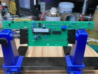
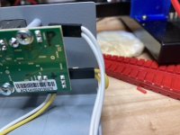
4. I was caught short with the mounting of the display, as I did not have any 2.5mm screws and 3mm standoffs in order to correctly position the display board at the correct height. I had to build four standoffs and keep them in place with some heavy gauge wire while I soldered the display in place. In the end I think I got the display slightly too high, as it rests against the case about 1mm before the screw standoffs, so there is a small gap between the control board and the standoff.
5. It was not immediately clear to me when putting together my BOM that the purpose of the 20-pin headers is to break bits of it off for several headers for the display and power sockets. Not a big deal, but it might help you when trying to find suitable replacements if the part cited in the BOM is not in stock.
For fit, orientation, and assembly:
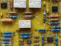
1. I was not sure of the orientation of the small electrolytic capacitors on the control board. It turns out that the square pad is positive, and the round pad is negative. (Googling this there does not seem to be a standard for this, so I could not answer it definitively.) I could not tell from the board pictures in the guide, but thankfully @gpapag posted their build pictures earlier in this thread, and it was much clearer.
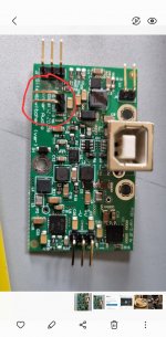
2. The orientation of U3, U2, & U5. The SMD parts have a line on them, which indicates the side of the chip that has pin 1. Googling this seemed to "suggest" that this was the case, but there was no definitive answer; even the data sheet for the exact parts did not indicate this. Again, it was @gpapag's pictures that helped clear this up! I have attached some pictures below with the correct orientation.
3. The height of the LEDs on the control board. I originally soldered these far too low; I then soldered them far too high. For reference, the base of the LED should sit just above the white of the button next to it. Again, pictures are attached below.
4. For the display, I originally had two full rows of header pins on the top and bottom until I looked more closely at the pictures. The top of the display has a full row of pins, while the bottom simply has two pins at either corner. I'm not sure if anything bad would happen if you soldered two full rows, but I thought it best to follow the build pictures. Thankfully I caught this prior to soldering everything in place.
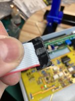
5. The assembled ribbon cable that I ordered (I did not have any ribbon cable on hand to make one) came with a bump on it, intended to fit inside of a closed socket to ensure a specific orientation. Unfortunately, this meant that there was no space between the header pins on the attenuator board and the chip socket for U1! I had to file the little bump down so that it fit. You might do this, or you might check to make sure you order a cable with no bump.
6. The assembly guide does not mention it but the user guide does: J6 and J7 are meant to provide additional voltage limit protection. It's not clear to me how these are jumpered -- are the two pins on each header jumpered (e.g., pin 1 to pin 2 on J6, pin 1 to pin 2 on J7) or if they're jumpered between them (e.g., pin 1 on J6 to pin 1 on J7, pin 2 J6 to pin 2 J7). I have left them unjumpered for now.
Finally, as the manual states, you may not see anything when you first power it up. Whatever you do, do not panic and post to diyaudio! 😎 Instead, make sure you turn the trimmer contrast adjust through it's full range (it's a multi-turn pot).
First off, let me say that this is a really good piece of kit. Everything seems top-rate, and despite some mix-ups with the Belgian Post it came on time and @jan.didden was very responsive to e-mail, even over Christmas. The instructions were pretty good as well -- certainly good enough for experienced builders. For intermediate builders, like myself, without deep parts bins, there are a few things that held me up during the build, so maybe this will help you out.
So, first off the parts that weren't in the BOM that you will need:
1. If you don't want to solder U1 and the control board chip directly to the board, you will need several chip sockets. 1x 28pin socket for the control board, and 1x 14pin socket for the attenuator board. If you are not using SMD parts for U2, U3, and U5 you will also probably want sockets for those. (8pin).
2. You will need a couple header pin jumpers for the headers on the control board for the display, and for the Silent Switcher to select the 5V mode. I didn't have any at hand, so I had to build a couple from a header-pin kit I had.
3. On that note, you will need to build or buy the header pin cables. You will need 2x 2-pin female to female (power switch and control board +5V), and 1x 3-pin female-to-female (attenuator board power). There are few links above this post to kits of jumper cables you can buy if you don't have any.
4. I was caught short with the mounting of the display, as I did not have any 2.5mm screws and 3mm standoffs in order to correctly position the display board at the correct height. I had to build four standoffs and keep them in place with some heavy gauge wire while I soldered the display in place. In the end I think I got the display slightly too high, as it rests against the case about 1mm before the screw standoffs, so there is a small gap between the control board and the standoff.
5. It was not immediately clear to me when putting together my BOM that the purpose of the 20-pin headers is to break bits of it off for several headers for the display and power sockets. Not a big deal, but it might help you when trying to find suitable replacements if the part cited in the BOM is not in stock.
For fit, orientation, and assembly:
1. I was not sure of the orientation of the small electrolytic capacitors on the control board. It turns out that the square pad is positive, and the round pad is negative. (Googling this there does not seem to be a standard for this, so I could not answer it definitively.) I could not tell from the board pictures in the guide, but thankfully @gpapag posted their build pictures earlier in this thread, and it was much clearer.
2. The orientation of U3, U2, & U5. The SMD parts have a line on them, which indicates the side of the chip that has pin 1. Googling this seemed to "suggest" that this was the case, but there was no definitive answer; even the data sheet for the exact parts did not indicate this. Again, it was @gpapag's pictures that helped clear this up! I have attached some pictures below with the correct orientation.
3. The height of the LEDs on the control board. I originally soldered these far too low; I then soldered them far too high. For reference, the base of the LED should sit just above the white of the button next to it. Again, pictures are attached below.
4. For the display, I originally had two full rows of header pins on the top and bottom until I looked more closely at the pictures. The top of the display has a full row of pins, while the bottom simply has two pins at either corner. I'm not sure if anything bad would happen if you soldered two full rows, but I thought it best to follow the build pictures. Thankfully I caught this prior to soldering everything in place.
5. The assembled ribbon cable that I ordered (I did not have any ribbon cable on hand to make one) came with a bump on it, intended to fit inside of a closed socket to ensure a specific orientation. Unfortunately, this meant that there was no space between the header pins on the attenuator board and the chip socket for U1! I had to file the little bump down so that it fit. You might do this, or you might check to make sure you order a cable with no bump.
6. The assembly guide does not mention it but the user guide does: J6 and J7 are meant to provide additional voltage limit protection. It's not clear to me how these are jumpered -- are the two pins on each header jumpered (e.g., pin 1 to pin 2 on J6, pin 1 to pin 2 on J7) or if they're jumpered between them (e.g., pin 1 on J6 to pin 1 on J7, pin 2 J6 to pin 2 J7). I have left them unjumpered for now.
Finally, as the manual states, you may not see anything when you first power it up. Whatever you do, do not panic and post to diyaudio! 😎 Instead, make sure you turn the trimmer contrast adjust through it's full range (it's a multi-turn pot).
Attachments
Andrew, thanks for a thorough write-up. These are things that you as the designer don't realize, but are real issues for the unsuspecting builder 😎
I'll see if I can rework the assembly guide.
BTW the trick to get the LEDs aligned is to first mount the front panel with the LEDs inserted but not soldered.
Then put the LEDs forward in their holes, then solder.
Jan
I'll see if I can rework the assembly guide.
BTW the trick to get the LEDs aligned is to first mount the front panel with the LEDs inserted but not soldered.
Then put the LEDs forward in their holes, then solder.
Jan
One thing that I don't see mentioned in this thread or the various guides is the issue of a dummy load. If I want to use this with a valve amplifier, should I also put an appropriately-sized resistor across the speaker terminals?
That totally depends on the amplifier. I am not a tube guy, but I understand that for a tube amp with an output xformer you should use a dummy load for the sanity of the amp.
In solid state it's less of an issue, but your measurement will be more realistic with a dummy load.
Jan
In solid state it's less of an issue, but your measurement will be more realistic with a dummy load.
Jan
I'm getting ready to switch this on but have a question about the silent switcher. It mentions to check the jumper for 5v, but the switcher I have doesn't have on and I can't find any reference to where this is?
Thanks, found it on the faq part on Jan's website.No, it's the one next to it -- with three pins.
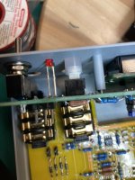
First switch on, relays click and screen displays this is this correct?
Attachments
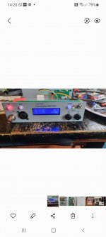
Looks good! Now interpret what you see ;-)
That's the first step to smart use.
Why does it go to max gain, +18dB, why is the green LED on?
Jan
That's the first step to smart use.
Why does it go to max gain, +18dB, why is the green LED on?
Jan
I need some help with this as its not working as it should, connecting Victors oscillator to this and nothing not registering any voltage in, and under voltage led always on, a mistake was made with diode D4 being installed the wrong way around, any ideas where to look now?
Lets do it step by step. Set the unit to single ended input, connect a known signal to the BNC input.
Check that a signal is going in at TP1 near the input (TP5 is ground).
Then check the signal at TP15 and TP16, they are found just between the two relays K5 and K7.
You can temporarily remove D4 to be sure it is not shorted. It's not needed for normal operation.
Jan
Check that a signal is going in at TP1 near the input (TP5 is ground).
Then check the signal at TP15 and TP16, they are found just between the two relays K5 and K7.
You can temporarily remove D4 to be sure it is not shorted. It's not needed for normal operation.
Jan
OK thanks for the help Jan.
So signal present at TP1 also at TP15 and TP16, although tp15/16 are at different amplitudes.
So signal present at TP1 also at TP15 and TP16, although tp15/16 are at different amplitudes.
OK, that's good. In the following, please put 1V into the SE input and set the unit to 0dB.
Then report signal levels when measured.
Did you check that there is output signal at the SE output connector?
If there is output, what is the level?
If you do not have output signal at the SE output, please check signal at:
TP18, 17 (just above and below relay K7);
TP19 (right of U5);
at the top of R15 (right of U3);
TP12, on the right of the flat cable connector, note this is a DC point! Check the DC level there.
Jan
Hi Jan,
So I've put 1vrms in, set to 0db and TP1 measures 1v, TP15 measures 1v TP16 nothing and yes I've an output from single ended at 1v
So I've put 1vrms in, set to 0db and TP1 measures 1v, TP15 measures 1v TP16 nothing and yes I've an output from single ended at 1v
That's perfect!
Please signal at the top of R15 (right of U3);
TP12, on the right of the flat cable connector, note this is a DC point! Check the DC level there.
Jan
Please signal at the top of R15 (right of U3);
TP12, on the right of the flat cable connector, note this is a DC point! Check the DC level there.
Jan
- Home
- Design & Build
- Equipment & Tools
- Autoranger for soundcards