Simulation in microсap shows that everything is OK. As practice too. To the parent topic (in Russian forum) added picture clipping.I just put this in spice, and it seems to be unstable when output signal is at 75% of Vcc, maybe we can repair this ?! I have seen this method in some paper, can not recall where: But here THD rises as frequency increases but it is always below UCD original. My simulation shows 0,0003% at 200 hz, 0,002 at 1 khz, 0,004 at 3 khz, 0,04 at 10 khz, but it is always better then original UCD.
Can you please link this N core design you made ?
Àâòîìîáèëüíûé ñàìîîñöèëëèðóþùèé âûñîêîêà÷åñòâåííûé ñòåðåî óñèëèòåëü 2õ100Âò
The attachment model modulator latest version. MC11
Here is the link to the ncore project. (approximately 20 pieces already manufactured) Óñèëèòåëüíûé ìîäóëü ïî ìîòèâàì ncore
I'm sorry - in Russian lang. 🙄
Attachments
Simulation in microсap shows that everything is OK. As practice too. To the parent topic (in Russian forum) added picture clipping.
Àâòîìîáèëüíûé ñàìîîñöèëëèðóþùèé âûñîêîêà÷åñòâåííûé ñòåðåî óñèëèòåëü 2õ100Âò
The attachment model modulator latest version. MC11
Here is the link to the ncore project. (approximately 20 pieces already manufactured) Óñèëèòåëüíûé ìîäóëü ïî ìîòèâàì ncore
I'm sorry - in Russian lang. 🙄
I can not open this with LT spice, what software should I use ?
But this Ncore is basicly UCd with integrator (UCD+) and symmetrical, I do not see benefit in this symmetry ?
What is the purpose of this "transistor circuit" at the feedback of integrator ?
Last edited:
New revision of the modulator (mdr 3_2)
What is the purpose of Q1 and Q2 ?
integrator amplitude limiterWhat is the purpose of Q1 and Q2 ?
i use microcap11.
differential modulator was designed to bridge output stage, but it works fine jointly half-bridge.
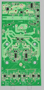
Symmetry is very important to suppress the output stage interference caused by nonoptimal PCB layout
Last edited:
integrator amplitude limiter
i use microcap11.
differential modulator was designed to bridge output stage, but it works fine jointly half-bridge.
Symmetry is very important to suppress the output stage interference caused by nonoptimal PCB layout
What would happen without that limiter ?
Output stage interference: Interference between what, please explain.
But if we have two identical class D amplifiers and connect them in bridge mode, would not this asymmetry be reduced?
New revision of the modulator (mdr 3_2)
Sous:
I made tests :
Old version mdr 1- 30 in spice gets lower thd then new version mdr 3_20, WHY ?
Sous:
I made tests :
Old version mdr 1- 30 in spice gets lower thd then new version mdr 3_20, WHY ?
The changes were introduced to improve the parameters at a high frequency. The previous circuit had a clearly expressed loop gain decrease above 1 kHz.
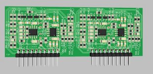
new, improved version
2x300W, distortion 1/10 max power less than 0.0015%, 1/2 power less than 0.004%
The output half-bridge is assembled IRS20957 and IRFB5615 transistors. The modulator is assembled on a comparator ad8561 and a differential opamp opa1632. The preamplifier used a circuit without capacitors in the sound, on the OPA1612, output on the opa 1632 and a servo in the loop of the preamplifier on lme49724.
Attachments
- Home
- Amplifiers
- Class D
- Automotive UcD high-quality power amplifier 2x100W