Is there a way to simply download the zip to my drive, I don't wish to log into anything to get the file.
I have checked again and I'm having no problem loading the .zip file without logging in to google (tested with Chrome and MS Edge). If the problem persists, please paste the error message that appears.
(BTW I'm getting a message from the Windows Defender that the file is rarely loaded and can be dangerous. There is nothing I can do about it, but it is still possible to save the file.)
(BTW I'm getting a message from the Windows Defender that the file is rarely loaded and can be dangerous. There is nothing I can do about it, but it is still possible to save the file.)
XMachina latest version: [1181114]
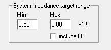
1) Introduction of upper limit for |Z| in the impedance target.
It's taken with less priority with than lower |Z| limit and dBspl targets. There is also an option not to apply upper limit in the LF region since it may require large values of reactances to do a selective correction there.
Short video to illustrate how it works. It's a shortcut of a design process showing dBspl and impedance curves converging to their targets.
- green: dBspl target,
- red: curret dBspl,
- orange: current |Z|,
- light blue: lower |Z| limit
- blue: upper |Z| limit.
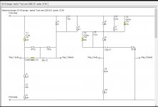
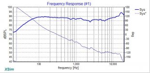
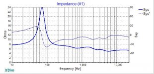
2) With the new version it’s possible to extend frequency range beyond the design range in the [Analyzer] window. Note that edge values of the characteristics are used, so it's only an estimation. It may help to spot some issues nevertheless. In the following example a low pass filtering was intended at the edge of tweeter band to suppress metal dome resonance at 26kHz. In the extended chart it appears to be implemented as a notch filter (green curve is the target, red is the result) which needs a slight correction to hit resonance frequency.
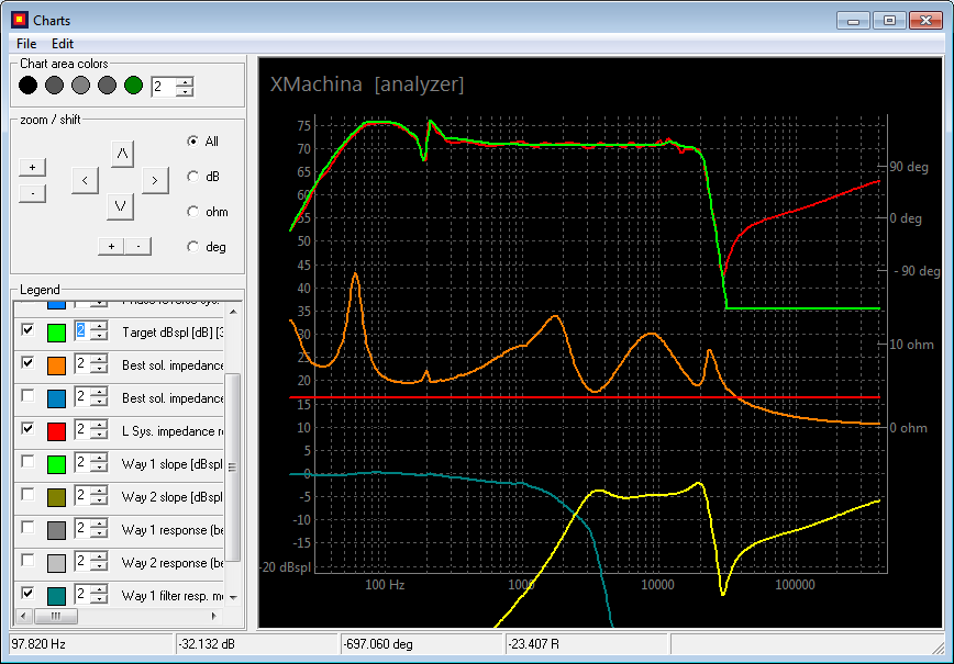
There is also an issue with the system impedance (orange), apparently filter circuit shorts amp output for high frequencies.
To extend freq. range for analyzer window right click on a completed design node then choose "Set freq. range for Analyzer" from the menu.
1) Introduction of upper limit for |Z| in the impedance target.
It's taken with less priority with than lower |Z| limit and dBspl targets. There is also an option not to apply upper limit in the LF region since it may require large values of reactances to do a selective correction there.
Short video to illustrate how it works. It's a shortcut of a design process showing dBspl and impedance curves converging to their targets.
- green: dBspl target,
- red: curret dBspl,
- orange: current |Z|,
- light blue: lower |Z| limit
- blue: upper |Z| limit.
2) With the new version it’s possible to extend frequency range beyond the design range in the [Analyzer] window. Note that edge values of the characteristics are used, so it's only an estimation. It may help to spot some issues nevertheless. In the following example a low pass filtering was intended at the edge of tweeter band to suppress metal dome resonance at 26kHz. In the extended chart it appears to be implemented as a notch filter (green curve is the target, red is the result) which needs a slight correction to hit resonance frequency.
There is also an issue with the system impedance (orange), apparently filter circuit shorts amp output for high frequencies.
To extend freq. range for analyzer window right click on a completed design node then choose "Set freq. range for Analyzer" from the menu.
Attachments


Hi,
Interesting piece of software. Thank you.
I think that your link still has the old version.
Jay
Interesting piece of software. Thank you.
I think that your link still has the old version.
Jay
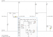
Hi all! Really a very interesting piece of software......I'm trying to simulate a very strange configuration and I do not know how to do it: the idea is two speakers in parallel to cover the lows, one speaker covering low mids, one for upper mids and a single tweeter. 2 problems arise, one is how to sim the pair in parallel and the other is that the software doesn't show the response from the 3 first speakers, actually shows like being disconnected. One picture is better to show it....
Attachments

Hi,Hi,
Interesting piece of software. Thank you.
I think that your link still has the old version.
Jay
Thanks for feedback. Link updated.
Last edited:
Hi all! Really a very interesting piece of software......I'm trying to simulate a very strange configuration and I do not know how to do it: the idea is two speakers in parallel to cover the lows, one speaker covering low mids, one for upper mids and a single tweeter. 2 problems arise, one is how to sim the pair in parallel and the other is that the software doesn't show the response from the 3 first speakers, actually shows like being disconnected. One picture is better to show it....
A few remarks on what I can read from the screenshots.
- The dBspl target curve starts at 100Hz and the first cross point frequency is 200Hz. I would suggest to extend the target dBspl curve at least to 20Hz, where your design frequency band starts. You can just follow your woofer characteristic (it's in the background in the target setup window).
- Creating low frequency cross points may require to extend component lists with appropriate values.
- In components application strategy settings "reduce large reactances" is chosen which may not be the best choice for ~200Hz cross point. First or second options seem to be more relevant in this situation.
- System impedance limit is set to 7R. Be sure to use 8ohm drivers for such setting, especially if you're aiming to achieve full dBspl from your drivers. If you want to use woofers in parallel you will have to apply 16R woofers. Or reduce minimum impedance target to 4R in case the woofers in parallel are 8ohm.
- Using 2 woofers connected in parallel as a single way is OK if .zma and .frd can be measured for such configuration.
- Possible reason for "disconnecting drivers": in 4- or more way system (I didn't try more than 5) there are usually large overlapping regions between drivers. Part reduction is one of the targets. If the filter slopes are moderate it may seem attractive for XMachina to remove the whole way, saving on components and making a small gap on the system characteristic. There are two ways to prevent such situation. Either reduce part removal intensity in task settings to keep moderate filter slopes, or increase the slopes so no way can be removed without making noticeable gap in the system spl.
- For 4 way design use at least "average" design time for testing task settings. When the results start to be good, use "detailed" design time option to get final solution.
How would you set up the "ways" for an MTM?
I have two woofers in series with their own FRD and ZMA files.
I have two woofers in series with their own FRD and ZMA files.
Confused about Schematic?
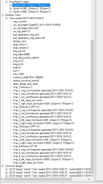
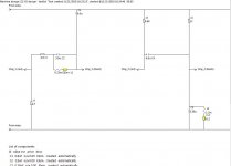
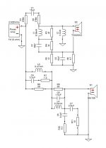
Here is the schematic from Machina and I cannot make heads or tales of it.
Can someone turn this into a schematic like I would use in Xsim or Vituix?
Here is the schematic from Machina and I cannot make heads or tales of it.
Can someone turn this into a schematic like I would use in Xsim or Vituix?
Attachments
Enjoy!Thanks for your feedback! I need time enough with your software, it deserves it!
Here is the schematic from Machina and I cannot make heads or tales of it.
Can someone turn this into a schematic like I would use in Xsim or Vituix?
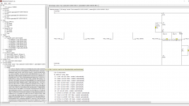
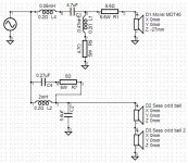
Some transformations may be applied to increase the readability of the schema.
The following equivalent circuit was obtained by swapping places of few components in branches. One of the amplifier's output was grounded.
Attachments
Xmachina can give solutions that a regular guy can't possibly come out with, not even in a million years. Then, is up to the user to choose the ones that are Ok, and discard the no-no ones (resistances in series with the woofer, very tormented Z module/fase, etc.) Besides, the filter presentation is a good oportunity to excersise into follow a circuit, what is in series or shunted with what, that you can re draw in a foil of paper, in Xsim, or other simulator.
Attachments

Last edited:
^Looks simple 😉 Component distributors might be interested in special versions which would create complex circuits only.
^Looks simple 😉 Component distributors might be interested in special versions which would create complex circuits only.
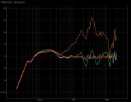
Circuits complexity can be adjusted in against the solution accuracy.
Let's take an example of a full range speaker having huge spl variations (orange curve). It's possible to get almost linear response (+- fraction dB, gray curve) with a complicated circuit (4xL 4xC).
Increasing the intensity of part reduction reduces the accuracy of the response (now it's c.a. +- 3 dB, green curve), but the number of components is reduced by half.
In general it may happen that the result is neither accurate nor simple. This is usually caused by issues in taget settings that make the task unsolvable. The most typical cases of such issues are described in the .pdf.
Attachments
Circuits complexity can be adjusted in against the solution accuracy.
Of course. My message was not so serious. Just reminded that long time ago Intertechnik was interested in distribution of VituixCAD while it was still commercial.
Anyway, response to listening axis alone does not necessarily define sound quality so much that it would be worth to optimize with unlimited amount of components. Problem is that user and system optimizer would need some constraints and knowledge how much each positive and negative feature and possible risks for example in directivity and different sources of IM distortion should be weighted to get optimized sound quality - whatever it means for each individual.
Thanks Mosquito, you seem to have control over the machine. Have fun!If You ask it kindly, it can give a simpler solution for the same driver combo of post #33
I was aware of that🙂. Just didn’t want to leave the impression that XMachian can do only complicated stuff.Of course. My message was not so serious. Just reminded that long time ago Intertechnik was interested in distribution of VituixCAD while it was still commercial.
Anyway, response to listening axis alone does not necessarily define sound quality so much that it would be worth to optimize with unlimited amount of components.
That’s right. At least some experience/knowledge is required to assess whether the circuit is worth the buck. It's a pity actually, because at the very beginnings of XMachina it was intended to be a straightforward application for DIYers that are not so experienced in circuits. Despite this the app seems to be (at least I would like to believe it) quite useful and it’s strongest point turned out to be an ability to coordinate goals from different domains (sys. dBspl, $ or complicacy reduction, impedance, slope control, phase adjustment at cross point and few targets still to come).
Problem is that user and system optimizer would need some constraints and knowledge how much each positive and negative feature and possible risks for example in directivity and different sources of IM distortion should be weighted to get optimized sound quality - whatever it means for each individual.
When working with XMachina it’s a very good idea to transfer most promising results to external tools for further analysis (and many thanks for VituixCAD by the way). New things may come to light, and this opens possibilities of extra modifications and tweaking.
- Home
- Design & Build
- Software Tools
- Automatic crossover designing with XMachina