"though I don't agree with his conclusion about good compensation for linearity."
Anatoliy,
What distortion problem are you concerned about? For non-linear loads, like a speaker maybe? I guess for this case, it would be best to go for absolute lowest output Z, so a bipolar transistor would be called for, since I see your "house warmer amplifier" uses this. Or a N-FDBK loop.
For just driving a grid, I would think class A, P-P, Mosfet should be pretty linear. Serious overkill really, unless driving a class A2 grid, but then that's back to non-linear loads.
Don
MOSFETs
Don't forget the Zetex ZVN0545A - Its a bit wimpy but if it will do the job then none of the larger devices will match it. I use it as a source follower to drive direct coupled output tubes grids (EL84, EL34, KT77)
I came across this device about 10 years ago in my day job when I was looking for something to switch 300 Volt gating pulses to a photomultiplier tube.
Data:
450 Volts
600mA peak 90mA continuous
600 mW ONLY (this will generally determine if it can be used or not)
BUT
Ciss is only 70pF, thats 1/2 what the best of the bigger devices will have.
It comes in an 'E-Line' package (TO-92 ish).
Cheers,
Ian
There is also a P channel Zetex too:
ZVP0545A 120pF 450V .7W gfs= .04 S TO-92
The Zetex's are a bit expensive though at $2.48/1, or $1.84/10 at Mouser anyway.
There are some surface mount SOT-223 Zetex's: ZVN0545GTA and ZVP0545GTA that are rated 2 Watts and are half the price of the TO-92 versions (Mouser prices again)
Also Fairchild has a TO-92L version
FQNL1N50B 500V 1.5 Watt 115 pF gfs = .55 S priced (at Mouser again) .45/1 .38/10
For driving non-linear class A2 grids, the higher gfs (Gm) of the FQNL1N50B would be a plus for lower output Z.
There are some Fairchild surface mount parts in the FQD... series and tabless heatsink mount parts in the FQU... series.
FQD1N80 FQU1N80 800V 45 Watt 150pF gfs = .75 S
For comparison, the whole bunch:
ZVN0545A (N channel) 450V .7 Watt 70pF gfs .1 S TO-92
ZVP0545A (P channel) 450V .7 Watt 120pF gfs .04 S TO-92
ZVN0545GTA (N channel) 450V 2 Watt 70pF gfs .1 S SOT-223
ZVP0545GTA (P channel) 450V 2 Watt 120pF gfs .04 S SOT-223
FQNL1N50B (N channel) 500V 1.5 Watt 115pF gfs .55 S TO-92L
FQP1N50 (N channel) 500V 40 Watt 115pF gfs 1.04 S TO-220
FQP1P50 (P channel) 500V 63 Watt 270pF gfs 1.26 S TO-220
FQP2P25 (P channel) 250V 52 Watt 190pF gfs 1.2 S TO-220
FQP2N90 (N channel) 900V 85 Watt 390pF gfs 2.0 S TO-220
FQP3P50 (P channel) 500V 85 Watt 510pF gfs 2.35 S TO-220
FQD1N80/FQU (N channel) 800V 45 Watt 150pF gfs .75 S D/I-PAK
Don
Just to be thorough:
Supertex DN2540 (N chan depl.) 400V 15 Watt 200pF gfs .325 S TO-220
The data sheet graph shows Cinput at about 168pF on a graph for drain voltages above 10 volts.
IXYS IXCP10M45S (N chan. depl.) 450V 40 Watt ?pF gfs .2 S (approx. at 100 mA) TO-220
IXTP02N50D (N chan. depl.) 500V 25 Watt 120pF gfs .15 S TO-220
I listed the IXTP02N50D since it is similar to the IXCP10M45S and does give the Cinput of 120pF for that. I would GUESS the IXCP10M45S Cinput to be about 180pF from the ratio of gfs for the two.
also the IXCP10M90S (N chan. depl.) 900V 40 Watt ?pF gfs .03 S (approx. at 100 mA) TO-220
The MUCH smaller gfs here would make me expect a lot smaller Cinput for this part, but no data is available.
A previous thread came to some conclusions on the Coutput (not the Cinput) here:
http://www.diyaudio.com/forums/showthread.php?postid=1220959#post1220959
With DN2540 at 28 pF
and IXCP10M45S at 125 pF
The similar IXTP02N50D however lists Coutput at 25pF. The discrepency may be due to the low drain voltage used in that measurement since the capacitance generally drops rapidly in the first 20V of drain voltage.
Don
OK, one more and I'm done beating this to death:
Gary Pimm used the IRF820B for CCS's, so I will list that. Actually the IRF820A had better input cap. specs, so I'll include that too.
IRF820A 500V 50W 340pF Cinput, 53pF Coutput, gfs 1.4 S TO-220
IRF820B 500V 49W 470pF Cinput, 45pf Coutput, gfs 2.9 S TO-220
For CCS use, I'll include the Coutputs for the earlier ones too:
ZVN0545 10pF
ZVP0545 20pF
FQNL1N50B 20pF
FQP1N50 20pF
FQP1P50 40pF
FQP2P25 40pF
FQP2N90 45pF
FQP3P50 70pF
FQD1N80/FQU1N80 20pF
Don
smoking-amp said:"though I don't agree with his conclusion about good compensation for linearity."
Anatoliy,
What distortion problem are you concerned about? For non-linear loads, like a speaker maybe? I guess for this case, it would be best to go for absolute lowest output Z, so a bipolar transistor would be called for, since I see your "house warmer amplifier" uses this. Or a N-FDBK loop.
For just driving a grid, I would think class A, P-P, Mosfet should be pretty linear. Serious overkill really, unless driving a class A2 grid, but then that's back to non-linear loads.
Don;
I'm concerned about odd harmonics; but I'm going to try your idea.
"going to try your idea"
The class A, P-P I guess? I haven't actually used that for driving tube grids, I just extrapolated from the SS class A amplifiers that have used it. One thing to look out for (I forgot to mention, but is obvious anyway) is the increased input capacitance when using a P channel Mosfet besides the usual N channel one, probably quadruple the input capacitance (and more if two CCS's are used for bias spreading).
But 90% or more of the cap. gets bootstrapped away anyway, and the available parts are pretty good now. I just ordered some FQP2P25 and FQP2N50 Mosfets, so I can try this out too. I may try the P-P buffer on the pentode plate to screen feedback scheme. Then later try putting some On-Semi Thermal-Traks on that to drive a speaker. I would like to see how much of the output circuit I can include in the screen feedback loop before it oscillates uncontrollably.
Guess I better include the FQP2N50 (TO-220) in the data list too:
FQP2N50 500V 55 Watt Cin: 180pF Cout: 30pF gfs: 1.45 S
FQP2P25 250V 52 Watt Cin: 190pF Cout: 40pF gfs: 1.2 S
These are the best match I can find between N and P channel Mosfets.
Don
I have read and reread this paper, and I have come to the conclusion that I must build an "acf-2" or an "acf-3" or both, only using somewhat BIGGER tubes. Then I must "test" it in true Tubelab style. As I am leaving town in a few days my "testing" will be confined to the simulation world for now.
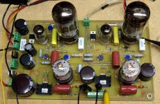
While visiting my very ill mother in law there wasn't too much to do since it was 2 degrees outside, so I did some simulations, designed an amplifier based on the ACF-2 and laid out a PC board. Now that I have returned and almost caught up on the usual stuff, I made one.
The amp used a 6EM7 to develop several hundred volts of clean drive signal, and feeds this into a Macdonald ACF-2 circuit that has been given the Tubelab treatment. The output tube is now the standard octal dual triode so I can use anything from a 6SN7 to a 6336A.
Initial testing with a 6SN7 revealed basic functionality, and several hundred volts (P-P) of clean output with no OPT hooked up. Connecting up an OPT caused red plates on the 6SN7. I popped in a 5998A which made about 2 watts before red plate set in. In true Tubelab style I went for the big guns and installed a 6336A. As soon as the tube warmed up both grid stoppers exploded in flames!
Far more science is needed when I am not in a rush, which means next weekend.
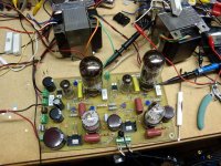
A picture of the PCB is included. Note the crispy resistor just in front of the right output tube. There is another one behind the yellow cap.
Attachments
Something obviously caused a bunch of grid current in the output tube all at once. It was late so I just turned it off. The DC voltages were not quite right with the smaller tubes in it, but I was in a hurry so I ignored that and cranked things up anyway.
The grids are DC coupled from a 12AX7 which is supplied by a 330K ohm plate load. There should be no way for this to source enough current to vaporize a 330 ohm grid stopper. It was either a serious oscillator or a tube arc. More experiments to follow. Toasted parts are likely!
The grids are DC coupled from a 12AX7 which is supplied by a 330K ohm plate load. There should be no way for this to source enough current to vaporize a 330 ohm grid stopper. It was either a serious oscillator or a tube arc. More experiments to follow. Toasted parts are likely!
It occured to me that the input capacitance is not too hard to measure on JFETs/Mosfets, so I tried measuring the IXCP10M45S.
A little tricky to remove the power supply capacitance and to get the correct voltage on the gate. I used a 9V battery and 10K pot. for neg. biasing the gate. I set it up at about 15 Ma.
Drain Volts ... Input cap.
0V 392pF
10V 315pF
15V 300pF
20V 289pF
30V 269pF
40V 252pF
50V 233pF
60V 216pF
70V 198pF
80V 184pF
90V 172pF
100V 163pF
150V 136pF
The IXYS device appears to be much slower at losing input capacitance versus drain voltage than the usual Mosfet data curves show.
I tried the DN2540N5 too, at around 15 mA:
0V 264pF
10V 101pF
15V 90pF
20V 83pF
30V 81pF
40V 79pF
50V 79pF
80V 79pF
100V 79pF
This looks more typical of the Mosfet data curves.
Appears the IXYS part needs to have higher drain volatage to get its input capacitance down. This is likely a clue to the large Cout seen previously at low drain voltage for the IXYS part.
For reference, I subtracted 10pF from all C meter measurements to get both these data sets. This was how much the C meter reading increased when I connected the power supply (set at 0 Volts), versus no power supply connected.
Don
Since the Supertex DN2540N5 measured a lot better than it's data sheet, and I had everything set up, I went and tried out the Fairchild FQP1N50 and here's what I got for input Cap. versus drain voltage at 15mA.
0V 167pF
5V 132pF
10V 113pF
15V 102pF
20V 95pF
25V 91pF
30V 89pF
35V 88pF
40V 88pF
50V 88pF
60V 88pF
70V 88pF
Better than the spec sheet too, and also dropping to a stable minium capacitance quickly.
Next, the P channel FQP1P50, input Cap. versus drain voltage at 15 mA.
0V 556pF
5V 461pF
10V 368pF
15V 356pF
20V 334pF
25V 320pF
30V 309pF
35V 301pF
40V 292pF
50V 280pF
60V 271pF
70V 263pF
80V 254pF
90V 247pF
100V 243pF
Data sheet says 270pF typical for 25V, but 350pF max for 25V.
I have been quoting the typical figure off the data sheets heretofore. The drop off in capacitance is slower versus drain voltage for the P channel part than the N channel part, the data sheet graph does show this too, but it looks a bit better than these measurements do.
Don
ITS ALIVE!
ITS ALIVE! And it works GOOD too. It turns out that the big dumb blonde one put 1N4007's in where the zener diodes should have gone. I replaced the toasted resistors, put some real zener diodes in and turned it on. It took a little adjusting, and the bias adjustments are real critical, but the amp works. How GOOD does it work? I am currently using 5998A output tubes. These are like higher gain 6AS7's. Output power at clip is 8 WPC. The distortion curves are unreal:
0.1 W .125%
1 W .175%
5 W .320%
6 W 1.4%
7 W 2.6%
8W 6.1%
Frequency Response @ 1 W:
Low End -3db point below 10 Hz
High End -3db point 26KHz
I listened to it for about an hour, it sounds GOOD, crystal clear, solid bass.
There are some issues, but the biggest one is that it still blows up when I plug in a 6336A.
Attachments

I did some more experimentation today. I realized that my distortion measurements were made with an HP 204C audio oscillator which has some inherent distortion, so I redid the measurements using the source in the HP8901A. I have not taken FFT measurements yet. The new numbers are:
.1 watt .119%
.5 watt .107%
1watt .132%
2watt .185%
5watt .285%
6watt .900%
7watt 2.47%
8watt 6.5%
The frequency response at 1 watt measurements were redone, and resulted in the same numbers. It was determined that the high frequency rolloff is caused by the Eastern Audio output transformers. A Transcendar OPT operating with a 1 ohm load on the 8 ohm tap was -3db at 35 KHz (although rather lossy). Low frequency response is still below measurement capability with 20 Hz only down .4db. No saturation effects were seen at 20 Hz and 5 watts although the power supply will go unstable when drawing 300 mA from it at frequencies below 40 Hz. It is an original Fluke 407D still operating with all of its bumble bee caps intact, so I allow it to misbehave sometimes.
And yes, I smoked a few more grid resistors trying to make the 6336A's work.
No more testing today, I just want to listen to it (before I blow it up again).
No more testing today, I just want to listen to it (before I blow it up again).
You know that I couldn't leave it alone. 6AS7's, 5998A's, 7236's all rolled through this amp without issue. I listened to each for about a hour. I began to think about the 6336A's, why wouldn't they work? What obvious thing could I be overlooking? How about the most obvious, a bad tube!
Yep, even though it worked in another circuit the 6336A that I tried was toast. 4 others from the same flea market box worked just fine. The ugliest two have been playing non stop for over an hour.
I don't have enough power supply to really test these tubes, but I see 8 watts at 0.4% distortion at 2.5% at 10 watts with both channels operating. The output impedance is about 1/2 an ohm.
Attachments

Hi,
Thanks to Jose, I get an e-copy of "Some Augmented Cathode Follower Circuits" written by Macdonald. I am very interested in the ACF-2 cirucit mentioned in this article.
Does another have a copy of "Active-Error Feedback and Its Application To a Specific Driver Circuits" (by Macdonald) that you want to share? I want to study the PACFD (parallel Augumented Cathode Follower Driver" discussed in this article in more details.
Thanks.
Regards,
T.C. MA
tcma@netvigator.com
snoopyma said:Does another have a copy of "Active-Error Feedback and Its Application To a Specific Driver Circuits" (by Macdonald) that you want to share?
Folks,
I also have this IEEE article published by Macdonald in 1955. Email me for a copy.
-- josé k.
- Status
- Not open for further replies.
- Home
- Amplifiers
- Tubes / Valves
- augmented cathode follower?