Tony said:hi,
what about cathode followers with constant current sinks in place of the cathode resistors?
anybody played with them?😀
Wright (read - Tectronix) fer instance
Tek actually used a three triode stack- a cathode CCS, the CF itself, and the upper bootstrap tube. They did a compensation trick there that I don't fully understand- I'll see if I can get a scan of a schematic posted.
reason i asked is i have these 6336 tubes that i would like to do a CF power output using an MJW18020D as current source, i reckon this trannie has morre than 30watt SOA at Vce of around 150volts.......😀
actualy weighing in heatsink size, versus a PL504 tube as current sink...
i thought the sandstate sink is cool..😀
actualy weighing in heatsink size, versus a PL504 tube as current sink...
i thought the sandstate sink is cool..😀
Seems to me that a high gm pentode would be a perfect candidate for the follower job. Even if we wire it as a triode it should behave like a pentode thanks to the constant voltage on both screen grid and plate.
reason i asked is i have these 6336 tubes
I have experimented with CCS circuits in the cathode of a CF. The CCS will keep the current through the CF constant as long as the AC load is light. It also helps with the asymetrical drive issue that a CF has since the CCS can sink a constant current up to its preset value. When you hang a heavy AC load on the CF (isn't that what we want them for?) the load line is no longer flat. A CCS loaded CF works well for driving an output tube grid where the current demands are also asymetrical.
When I started down this CF output stage path six or eight months ago I new that I was going to use some type of constant voltage circuit. Thus I needed to find a tube that would work well with a fixed low voltage across it. I also wanted a tube that could handle a lot of current (hundreds of mA) so that I could use a low impedance OPT (600 ohms) and eventually do an SE OTL. I set up a test fixture and ran through a bunch of different tubes, captured data, and plotted the linearity VS current for a fixed voltage. The clear winner for this application was the 6336A. In second place a triode wired 6LW6. I did not test the Russian 6C33C since I do not have suitable sockets.
If you want to experiment with CF output stages using 6336's stack your follower on top of the output CF and do an "augmented design". If you are not in a big hurry, I will post my schematics after I get it all working correctly. There will be a version with 6336's, but I will probably use a mosfet for the top device due to SOA failures with BJT's. I plan to run the total B+ in the 350 to 400 volt range to achieve 20 to 30 watts.
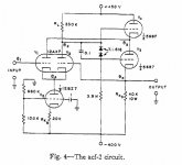
I am enclosing the ACF-2 circuit from the Macdonald publication. I don't have much time since I am leaving town on the 26th but I have built one of these with the following changes. I substituted a CCS IC for V5, V1 - V2 is a 6SN7, and V3 - V4 is a 6AS7. It works, but I have not had time to do much testing. I could not get it to work with a 6SL7 for V1 - V2.
Attachments
what about cathode followers with constant current sinks in place of the cathode resistors?
anybody played with them?
I built a preamp based on Allen Wrights FVP5. It uses a simple triode as a primitive CCS, and a mosfet as the Constant voltage element on top. Its really quite simple to implement and I noticed improvements on each stage of its evolution from a simple CF buffer stage. Allen Wrights offerings are highly respected, and my version was very well received at a recent meet.
Allen Wright claims that its real sonic benefit is in removing the feedback element of the cathode resistor in a normal CF. Don't know myself 🙄
There is a brief mention of the circuit over on the Tubcad archive, he implements a very interesting low voltage version using ECC86's, I think the B+ is only 24V. This removes practically all the complexity associated with this circuit approach and because of the extremely linear nature of this circuit - I would feel confident that it would give up little to a higher voltage version.
I intend to do further refinements but am convinced in the approach. It presents an extremely uncoloured but mellow sound - which is exactly what I expect from valves.
Shoog
SY said:Tek actually used a three triode stack- a cathode CCS, the CF itself, and the upper bootstrap tube. They did a compensation trick there that I don't fully understand- I'll see if I can get a scan of a schematic posted.
Were you able to find that Tek schematic?
Dave

That is an interesting circuit, what is the source? However, it isn't the Tek circuit that SY mentioned. From SY's post, it was a lot more complex.
Dave
Dave

The circuit in post #28 comes from the book "Typical Oscilloscope Circuitry, rev. ed." by Tektronix. The bootstrap cap is acting only at high frequency (like a neutralization cap for P-P) to null out the effect of intrinsic plate capacitance Cp of V1. Putting in a bigger cap will make it increase gain to full Mu over the whole BW like a CCS plate load on V1.
The circuitry C116,C117 in Sy's post appears to be doing the same thing. R118 being put in so the caps have some HF bite on the signal. What is curious is C113 and R113 which appear to have the opposite affect.
These Tek circuits would appear to be acting in the MHz region, so not really useful for audio unless one is using a really wimpy driver tube, like a 12AX7 trying to drive some huge regulator triode for OTL.
Don
Thanks for the post SY.
The definition of gm is a small change in plate current divided by a small change in grid voltage with the plate-to-cathode voltage held constant. It would seem that if we were to find a tube with constant gm, and held its plate-to-cathode voltage constant, this is exactly what we would want for a cathode follower. So, my first question is: “what tubes have a constant gm?”
In addition to holding the plate-to-cathode voltage constant, the MacDonald paper uses a CCS in the cathode follower. The Tektronix circuit also uses a CCS in addition to holding the plate-to-cathode voltage constant. It would seem from the gm definition that constant current should not come into play here, but some smart designers have included it, so I am missing something. My second question is: “what is the advantage of holding the current constant in a cathode follower when the plate-to-cathode voltage is also held constant?”
Dave
The Gm is not constant for any tubes to a first approximation unless the current is held constant:
Gm = k*Ip^(.33333)
So thats the reason for the CCS in the cathode circuit.
If one puts a real (resistive) load on the CF, then the CCS is not the final answer however, since the load will vary the cathode current.
Then either a standard White CF or a modified version of the White CF is needed (for the plate follower on top of the CF case).
The modified WCF would use a resistor/cap from the CF output down to the CCS cathode/source to null out current variation in the CF from load.
Rising output voltage then causes the CCS to drop current at the same rate that the load picks up current. Haven't seen anyone use this, but should be standard audio practice for low distortion.
Don
Well, mu enters into that, does it not? It is degenerated, after all.
The reality is, with a properly designed CCS-loaded plain vanilla cathode follower running into an appropriate load, I can't measure the damn thing, it's so linear. Can't hear it in the signal path, either.
At that point, I stop worrying too much about reducing CF nonlinearity. 😀
The reality is, with a properly designed CCS-loaded plain vanilla cathode follower running into an appropriate load, I can't measure the damn thing, it's so linear. Can't hear it in the signal path, either.
At that point, I stop worrying too much about reducing CF nonlinearity. 😀
Don, regarding the compensation, it looked to me like the resistor voltage divider ratios were odd. I could see them the other way round because of the tube mu. So clearly I'm missing something fundamental. Can you explain the ratios? One hint may be that the adjustment cap was supposed to be for overload recovery.
Hi Stuart,
Which resistors? R119,R118 (I can't really read all the R#s in the post, but referring here to the two R's going to the V114a grid, other than the 100 Ohm grid stopper R116)? I think R118 is just to get the RC constant adjusted for C116/C117. To make for some HF peaking affect by boosting V114a drive.
Yes, totally agree on the Mu degeneration/feedback minimizing varying Gm effects. But then the old tube designers didn't have Audio Precision analyzers that could see .001% distortion back then either. Just a minor tweak (an R and a C) to put some compensation into the CCS for load effects.
I guess with the top plate follower, one could say the CF Mu goes to infinity....., so no need to compensate the CCS current for constant Gm.
Geez, getting so complicated, why not just use a Mosfet for the CF, so much simpler! FQP1N50 50 cents, replace the whole thing.
Don
Sy,
Oh.., I think I may see what you are getting at about the resistor divider ratio and the top tube's Mu. By putting the bootstrap to the V114a plate instead of effectively to its grid (by going back to the previous driver stage plate load, like in the Tek diagram I posted). Could be some math relationship, I would guess they just calc'd the RC time constant they needed though, or more likely just adjusted some pot to get a square wave's corner cleaned up. I see a square wave scope trace on the daigram with an arrow pointing to the CF output.
Don
Yes, the 750k and the 63k4. I can understand bypassing the 63k4 thoroughly to maximize the gain of the upper tube (since it's mu/(1+mu), slightly lower than unity). But why cut the gain further, slightly modulate the Vak of the cathode follower, then bring it back at very high frequencies to unity? And what has that to do with overload recovery?
Since it's Tek, I know for sure that it's me who's not seeing something.
Since it's Tek, I know for sure that it's me who's not seeing something.
"But why cut the gain further, slightly modulate the Vak of the cathode follower, then bring it back at very high frequencies to unity?"
Probably just a compromise, can't get the extra gain for peaking without dropping it some for the main signal a little. Just guessing.
Should be something in the service manual for the scope about what the adjustment is doing. Looks like a square wave corner peaking adjustment to me with that scope trace annotating it.
What scope is that anyway? Tek 545?
Don
- Status
- Not open for further replies.
- Home
- Amplifiers
- Tubes / Valves
- augmented cathode follower?