Hi Peter, I'm thinking about copying your patak enclosure design for my lm4780 kit. Would heat be an issue with the higher power output of this chip? Also I noticed that the side pieces seem to be made of solid wood in some pictures, but not in all of them. The other pictures seem to suggest you made an insert of aluminum for the side that covers the caps. Just curious about this, and which way you have decided to go.
Here's the links to the pictures to help clarify.
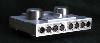
No aluminum http://www.audiosector.com/images/patek/Patek3.jpg
Insert http://www.audiosector.com/images/patek/Patek11.jpg
Here's the links to the pictures to help clarify.
No aluminum http://www.audiosector.com/images/patek/Patek3.jpg
Insert http://www.audiosector.com/images/patek/Patek11.jpg
It's not the insert, it's nickel conductive paint. I only made few amps like that initially, all other amps use dual side panels (Patek v2).
The inside panels are from maple, sprayed with conductive coating; the outside panels are exotic wood, usually Maccasar Ebony.
The chassis can probably dissipate 2 x 5W of continuous power (100Hz sine wave into dummy load). It works well in real live with LM3875 chip, without any overheating issues. If you want to use LM4780 chip for more power, that chassis may be too small.
I'm presently also using bottom panel for heat dissipation, it is attached to copper bar through aluminum block.
jleaman said:What is the total price for the kit then with led display and kit,
Untill I am in position to secure reliable supply of display modules, I won't be offering that circuit as a kit. Presently, only PCBs and control chip are available. If you are able to source all the other parts yourself, you can complete that project.
Member
Joined 2002
Peter, at this time what are you curenly using for a pre-amp ? is it passive or buffer ?
I'm currently using one of Brent's buffer with my Aleph's. I'm impressed, but wondering what you use ?
I'm currently using one of Brent's buffer with my Aleph's. I'm impressed, but wondering what you use ?
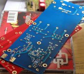
BTW, I received the USB DAC boards today. I will be building one tomorrow to see if everything works fine.
Peter Daniel said:BTW, I received the USB DAC boards today. I will be building one tomorrow to see if everything works fine.
Ahhhh....thats what I've been waiting for! Let us know how it goes.
Robert
Member
Joined 2002
Peter Daniel said:I was using all sort of different pieces, but eventually I'm coming back to TVC: it is my current opinion that it is the most neutral line stage. The gain is limited to 6dB only, so it's not really completely passive.
Very nice, of course out of my price range 🙁 i'm running passive and Brent's buffer. i'm loving the passive with the nice alps pot i have, i'm curious to see if i get the same results with your relay based one.

I took my two cased P. Daniels Premium NOS DACs to the 2007 International HeadFi meet in San Jose last weekend (see setup picture...I used the black/wood cased one on the top). I took the digital out from a Marantz DV9600 as a source into the DAC, then to an AMB M3 headphone amp and Sennheiser HD650s as one of my displayed DIY systems. It was very well received by those who tried it, and quite a few did.
Most of the attention was on the Manufacturers who turned out in force, but the DIY crowd made a good showing in one end of the main room.
HeadFi
Most of the attention was on the Manufacturers who turned out in force, but the DIY crowd made a good showing in one end of the main room.
HeadFi
Hey all.
I've finally started assembling my DAC board (can't beleive I was afraid of SMD soldering !), and am almost done, but noticed on the board there are two resistors not on the schematic, R11 and R12 (which go between the output and ground).
What values should they be ?
I've finally started assembling my DAC board (can't beleive I was afraid of SMD soldering !), and am almost done, but noticed on the board there are two resistors not on the schematic, R11 and R12 (which go between the output and ground).
What values should they be ?
Those are optional output caps bleeder resistors. I normally don't use them, if you want to intall them a value around 50K would be fine.
Transformer wiring for Lm3875 kit
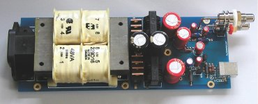
I have 4 EI transformers that I got for basically nothing, they are: 120v primary 12.6 - 0 - 12.6 v secondary, 2A
These are centertapped. I realize these probably dont have a huge VA rating but I would like to try them since I have them laying around (and I have 4 is it possible to use them all to boost VA?)
What is the best way to wire these up to Peter Daniel's lm3875 PS boards?
It's best to use one transformer per rail. That would mean 4 transformers per stereo amp.
The secondaries would be connected in series (25 V per transformer); one transformer connects to AC1-AC1, the other to AC2-AC2 (centetrap not connected).
The secondaries would be connected in series (25 V per transformer); one transformer connects to AC1-AC1, the other to AC2-AC2 (centetrap not connected).
I have a quick (probably stupid) request. Could anybody provide me with a picture of a bridged lm4780 board? For some reason I'm just not grasping the concept of how to do it properly.
The picture was posted here: http://www.diyaudio.com/forums/showthread.php?postid=636565#post636565
Bridged configuration is exactly same as stereo. The concept has been explained on page 8 of F4 manual: http://www.passlabs.com/np/F4 Power Amplifier.pdf
Bridged configuration is exactly same as stereo. The concept has been explained on page 8 of F4 manual: http://www.passlabs.com/np/F4 Power Amplifier.pdf
Peter,
Have you posted your impressions of the USB version of your dac? I'm curious as the schematic looks greatly simplified (no SPDIF!! conversion needed!). The board looks beautiful, on my short list to order, even though I'm enjoying your SPDIF version of your dac. Lots of PRAT!
Anand.
Have you posted your impressions of the USB version of your dac? I'm curious as the schematic looks greatly simplified (no SPDIF!! conversion needed!). The board looks beautiful, on my short list to order, even though I'm enjoying your SPDIF version of your dac. Lots of PRAT!
Anand.
- Status
- Not open for further replies.
- Home
- More Vendors...
- Audio Sector
- AudioSector-chip amp kits, dacs, chassis