Help w/3875 power supply
This is embarrassing... Peter, I ordered one of your kits quite a while ago to build for a friend (last summer?). Turned out the kit ended up being for me, but one thing led to another and I've never finished it...
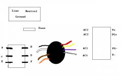
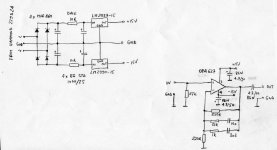
This is the premium LM3875 kit, which I was trying to put together as a dual mono amp, passive volume and chipamp in one chassis, and two separate chassis for each channel's power supply. Also, the main thing that was giving me trouble was, I'm trying to wire it up with a DPDT switch to switch from 120V to 230V mains. The trannie I'm using is:
http://www.plitron.com/shopping/specs/0770XX201.pdf
300VA with 24V secondaries.
So I thought I knew how to wire it together, and I plugged everything in, and 'POOF!' The fuse blew and there was a loud sound from the speaker (I only wired it up for one channel). I hope I didn't do any damage to the amp.
I've come to the conclusion, that even though I've done a little diy'ing, I'm out of my depth here... the instructions don't cover what I'm trying to build. (If worse comes to worst, I could ditch the DPDT switch).
Could one of you kind souls take a look at this little diagram and tell me what hooks up to what? I need some remedial help here.
It may just be the DPDT switch. Thanks.
This is embarrassing... Peter, I ordered one of your kits quite a while ago to build for a friend (last summer?). Turned out the kit ended up being for me, but one thing led to another and I've never finished it...
This is the premium LM3875 kit, which I was trying to put together as a dual mono amp, passive volume and chipamp in one chassis, and two separate chassis for each channel's power supply. Also, the main thing that was giving me trouble was, I'm trying to wire it up with a DPDT switch to switch from 120V to 230V mains. The trannie I'm using is:
http://www.plitron.com/shopping/specs/0770XX201.pdf
300VA with 24V secondaries.
So I thought I knew how to wire it together, and I plugged everything in, and 'POOF!' The fuse blew and there was a loud sound from the speaker (I only wired it up for one channel). I hope I didn't do any damage to the amp.
I've come to the conclusion, that even though I've done a little diy'ing, I'm out of my depth here... the instructions don't cover what I'm trying to build. (If worse comes to worst, I could ditch the DPDT switch).
Could one of you kind souls take a look at this little diagram and tell me what hooks up to what? I need some remedial help here.
It may just be the DPDT switch. Thanks.
Attachments
Unless you plan to use transformer with 230V I would not recommend any DPDT switch on primaries. Here's the link to Plitron connection diagram : http://www.plitron.com/standard_schematics.asp
All the other info you will find here: http://www.diyaudio.com/forums/showthread.php?s=&threadid=94300
Before connecting amp to PS check for correct voltages first, before connecting speakers to the amp, check for DC offset (it should be below 100mV on speaker terminals)
All the other info you will find here: http://www.diyaudio.com/forums/showthread.php?s=&threadid=94300
Before connecting amp to PS check for correct voltages first, before connecting speakers to the amp, check for DC offset (it should be below 100mV on speaker terminals)
dual RCAs in DAC
Hi Peter,
Do you know if these Vampire pcb mount dual RCAs fit your DAC boards (w/o mods that is)?
http://vampirewire.com/mcart/index.cgi?code=3&page=2&cat=5
(Towards the bottom of the page)
Thanks,
Ryan
Hi Peter,
Do you know if these Vampire pcb mount dual RCAs fit your DAC boards (w/o mods that is)?
http://vampirewire.com/mcart/index.cgi?code=3&page=2&cat=5
(Towards the bottom of the page)
Thanks,
Ryan
The first dual RCAs on a page (Part #PC2V ) will fit the Green board. The gold board accepts only Cardas dual connectors. You can also make them yourself:
An externally hosted image should be here but it was not working when we last tested it.
An externally hosted image should be here but it was not working when we last tested it.
An externally hosted image should be here but it was not working when we last tested it.
An externally hosted image should be here but it was not working when we last tested it.
Peter,
just to say that i'm wainting for your phonostage 😀
Next month i'll probably buy your DAC.
just to say that i'm wainting for your phonostage 😀
Next month i'll probably buy your DAC.
I'm actually working hard with phonostages. I started with a phono section based on VSPS (RIAA circuit only with all the rest changed and OPA627 used) and it worked surprisingly good. The step up was done by S&B TX103 (for Shelter 901)
If there is an interest, I can post detailed schematic.
If there is an interest, I can post detailed schematic.
Attachments
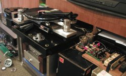
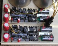
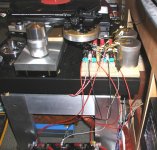
The second circuit I tried was ONO. I used what I thought the best parts and because I couldn't decide which version of PS to choose I run it from batteries. But I was not blow away after switching from OPA627 circuit, in some ways I think the other one was smoother. I may have overdone with all those Premium part in ONO ;-)
Attachments
paulomartires said:And some sort of Phonocube (Phonoclone)?
RJM offers such thing, so I will not pursue that avenue.
Here is the schematic of VSPS based phono stage using Allen Wright's modified curve, with the additional zero at 3.2 µS.
The component types are probably critical and are based on my previous experiments with DAC and buffer. Good thing was that most of the parts came from my other projects as well. All resistors are Caddock MK132, RIAA caps are 10n ERO 1830 and 3n3 Wima FKP2. I use separate transformer per channel: Hammond 229D24. The only bypasses after regulators are BG N 4.7/50. If you select OPA627 for low offset you may not need output coupling cap (offset less than 2mV).
This is actualy a very good sounding circuit. It is also simple enough to be built on a proto board.
Attachments
Hi there Peter!
I'm just about to add a much-needed heatsink to my Audiosector Gainclone. I'm using a piece of quarter inch thick copper plate, and the size is approx. 4" x 3.5".
Having never attempted to drill holes in copper plate before, is this do-able just using a standard electric drill with perhaps a bit of oil or methalated spirit to aid the cutting action of the drill bit?
Lastly, once done and I've polished the copper up, is it just a case of lightly sealing it with some spray metal lacquer or is this not necessary? Does the lacquer inhibit the heat-absorbing qualities of the copper at all?
Cheers,
- John
Drilling in copper is about the same as drilling aluminum, just slightly harder, so your regular tools shoul dbe fine.
Sealing with laquer is a good idea, one product is specifically suitable for that purpose: http://www.krylon.com/main/product_...elid=8&productid=1816&content=product_details
I also used Danish Oil for protecting copper and it worked well. Those finishes should not affect thermal dissippation as long as the areas where chip installs and copper connects with the rest of the chassis are not covered.
Thanks for the super-speedy reply Peter 😀 Thanks also for the masking tape tip Brian.
I'll get drilling and polishing then!
Thanks a mil!
- John
I'll get drilling and polishing then!
Thanks a mil!
- John
Pass Ono boards and power supply
Peter Daniel:
I was wondering if you sell PCBs for either the Pass Ono or the associated power supply. Someone referred me to you and figured this was the proper place to ask 😀
Thanks!
Peter Daniel:
I was wondering if you sell PCBs for either the Pass Ono or the associated power supply. Someone referred me to you and figured this was the proper place to ask 😀
Thanks!
I don't sell them, but recently ordered 2 sets, so one may be available. But not earlier than a month or so.
- Status
- Not open for further replies.
- Home
- More Vendors...
- Audio Sector
- AudioSector-chip amp kits, dacs, chassis