Sure I prefer wood, but this one is easier to make. This is for AudioZone DACs, and it matches Amp-1 appearance. My personal unit is without any case, just resting on a piece of acrylic.
With a board in a metal case, the sound becomes a bit less open. Not a bigh difference, but still noticable.
With a board in a metal case, the sound becomes a bit less open. Not a bigh difference, but still noticable.
Peter,
What method are you using to transfer the "DAC-1" lettering to the aluminum plate? Been trying to figure out how I'm going to get lettering on my pre-amp chassis!
Terry
What method are you using to transfer the "DAC-1" lettering to the aluminum plate? Been trying to figure out how I'm going to get lettering on my pre-amp chassis!
Terry
I'm using dry transfer method and sheets with lettering can be bought at graphic supply outlets: http://www.diyaudio.com/forums/attachment.php?s=&postid=62789&stamp=1032685651
Soon a new board will be available from AudioSector.com
It is a replacement for a previous parallel only LM4780 board. The new board allows all 3 configurations: stereo, bridged and parallel.
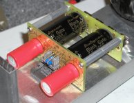
I'm testing it presently in a stereo version, and it sounds very good. The price of the new board will be $25, featuring as usually 2 amp channels, as well snubber option for PS. I will be also offering half of that board only (for half the price), allowing to build a stereo amp (like the one in a picture), using one LM4780 chip.
Copper spreader was used to improve heat release from a chip.
It is a replacement for a previous parallel only LM4780 board. The new board allows all 3 configurations: stereo, bridged and parallel.
I'm testing it presently in a stereo version, and it sounds very good. The price of the new board will be $25, featuring as usually 2 amp channels, as well snubber option for PS. I will be also offering half of that board only (for half the price), allowing to build a stereo amp (like the one in a picture), using one LM4780 chip.
Copper spreader was used to improve heat release from a chip.
Attachments

Here's a closer look at the complete assembly. 1000/50 caps are mounted directly to rectifiers board and that board is attached to amp's board using standoffs, forming a one piece module. 100/50 caps are mounted directly at the chip and all the connections are minimized.
Attachments
Received the DAC kit on friday, immediately started soldering. Fairly easy job, only the SMD regulator was a bitch because I lost my tweezers. Everything checked, looked OK so plugged it in, but it remained dead silent  . It appears I have a short between +UD and DGND, but I cannot trace it, everything looks ok, so probably I have a cap with a short or something...
The dales still measure 20 Ohms and the C3 is being charged 'properly' (too low voltage due to short). After two days of checking still can't find it... I hope tomorrow...
. It appears I have a short between +UD and DGND, but I cannot trace it, everything looks ok, so probably I have a cap with a short or something... The dales still measure 20 Ohms and the C3 is being charged 'properly' (too low voltage due to short). After two days of checking still can't find it... I hope tomorrow...
Check all the voltages first. You should have approx 10V between R1/R2 and R3/R4 and then check all voltages after the regulators: 5V in 3 places and 8V on a DAC chip. One of the Canadian customers already built the DAC and it worked fine. He actually had a problem with a fuse, but after replacing it, the DAC worked OK.
I've found the defect. UA was the proper 10V, UD=0V, at the trafo side of the dale resistors it was 11,5V. By disconnecting L3 and L4 and later the Oscon C15 I found I have a short between IN and GND of U1. I really cannot see a incorrect joint or malfunction in the PCB so my guess is that this unit is defective. I will try to locate an AN8005 at a local dealer to replace it. I hope that will solve the problem...
Hanzwillem said:I've found the defect. UA was the proper 10V, UD=0V, at the trafo side of the dale resistors it was 11,5V. By disconnecting L3 and L4 and later the Oscon C15 I found I have a short between IN and GND of U1. I really cannot see a incorrect joint or malfunction in the PCB so my guess is that this unit is defective. I will try to locate an AN8005 at a local dealer to replace it. I hope that will solve the problem...
You might have heated up the regulator too much when soldering them to the pcb. I had a similar problem soldering small transistors to my original Mini-A layout, and eventually decided to just solder the TO-92 part on the SMD pads.
--
Brian
I hope so, I do not like the receiver chip to be broken. According to my solder station it is soldering at ~600F/320C, but maybe it was too long...
Hanzwillem said:I've found the defect. UA was the proper 10V, UD=0V, at the trafo side of the dale resistors it was 11,5V. By disconnecting L3 and L4 and later the Oscon C15 I found I have a short between IN and GND of U1. I really cannot see a incorrect joint or malfunction in the PCB so my guess is that this unit is defective. I will try to locate an AN8005 at a local dealer to replace it. I hope that will solve the problem...
U1 powers SN75179 only. It should not affect receiver. I will send you both AN8005 and SN75179 tomorrow.
Thanks a lot for the effort Peter!
I replaced U1 with a 78L05 and it works fine now. Just plugged it in.
So if you think ST's 78L05 won't make much difference for the receiver buffer (couse I think it would make much difference) then please don't bother sending me an an8005 and keep the components and money in your own pocket 🙂
Thanks a lot for the kit, it looks absolutely amazing and sounds so too. I will do a lot listening in the next days I think 🙂
Thanks again! I will post a picture when the bottom plate is finished (22mm MDF on spikes, maybe some alu panels to reinforce the connectors)
I will send you that regulator anyway, as I suspect it may make a difference 😉 You should receive it in 3 days or so. Glad you sorted out that problem.
Message to Hanzwillem
Hanzwillem,
You have disabled the option to contact you tru email on this board so i post my request here:
I live close to you (Deventer) and i would appreciate if i could listen to the DAC of Peter.
Something like "If you show yours I'll show mine" (not really!)

Another dac and perhaps the premium LM3875 kit ?
If that would be interesting to you i would really appreciate if you could contact me tru my profile
Gerben
Hanzwillem,
You have disabled the option to contact you tru email on this board so i post my request here:
I live close to you (Deventer) and i would appreciate if i could listen to the DAC of Peter.
Something like "If you show yours I'll show mine" (not really!)
Another dac and perhaps the premium LM3875 kit ?
If that would be interesting to you i would really appreciate if you could contact me tru my profile
Gerben
I have disabled that? Hmmmm, dat was niet de bedoeling...
Yes, this is very well possible. Let us make arrangements for that.
Yes, this is very well possible. Let us make arrangements for that.
DAC and PC Sound Card
I would like to build your DAC and use it with my PC. What sound card would I need to have digital outputs to connect to your DAC?
The reason for this is to rip all my CD's to Media Player and then use my PC when listening to CD's.
Thanks...
Bruce
I would like to build your DAC and use it with my PC. What sound card would I need to have digital outputs to connect to your DAC?
The reason for this is to rip all my CD's to Media Player and then use my PC when listening to CD's.
Thanks...
Bruce
You can use any soundcard that provides SPDIF output. You might be even OK with optical output, but that needs some mods to the board (adding toslink receiver).
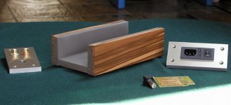
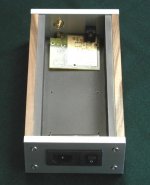
I was working recently on a different enclosure for a DAC, and here's how it looks.
The side panels are made out of Red Gum wood, the bottom made of Balic Birch and thin metal plate attached (mostly for cosmetic reasons). Front and rear panels are machined from 3/8 aluminum and alodined.
The side panels are made out of Red Gum wood, the bottom made of Balic Birch and thin metal plate attached (mostly for cosmetic reasons). Front and rear panels are machined from 3/8 aluminum and alodined.
Attachments
- Status
- Not open for further replies.
- Home
- More Vendors...
- Audio Sector
- AudioSector-chip amp kits, dacs, chassis