Bought an Audiolab 8000A bout 20 years ago. The MM phono stage has never worked (tested with two known good turntables). I have never owned a MC turntable so I have no idea if that stage is functioning. I would now like to get at least the MM stage working so that I can route my turntable through the Audiolab instead of through a second Arcam amplifier that sits alongside. I have the 8000A service manual, a DVM and can read a circuit diagram and identify components. Beyond that my electronic equipment fault finding skills are very limited. Suggestions where to start fault finding would be appreciated. There is also some low volumes hiss on the left channel when using other inputs such as CD player and SlimDevices, not loud enough to be discernible at listening volumes but noticeable between tracks.
It's very unusual to have small signal faults in circuitry.
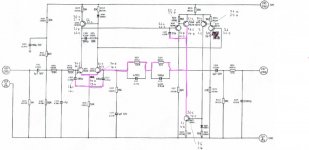
The things to check are that the MM stage has power which seems to be a single ended 30 volt rail.
Next check is with the amp OFF and to check continuity from the output of the MM stage to the input switch and from there onward to the line and tone stage. Given that other inputs are OK the 'onward' bit must be OK.
Thank you for the quick response. Have done the suggested checks: the 30V supply is present and both channels have continuity from the stage output through the selector switch to the tone stage. Continuity also checked from phono connectors to MM stage input. Connected everything back up to check I hadn't created some other fault along the way and now find that one channel of the MM stage is working but not the other.
Back to the bench - checked all caps for short circuit, all good, all diodes ok. I don't have a DVM capable of measuring small AC voltages - for what it is worth (probably nothing!) the output on both stages is about 19mV DC with the turntable playing into the input.
Working on the premise that I have one good channel, is it worth probing around the transistor emitters with the voltmeter to see if there is a gross difference between like-for-like transitors on the good channel and the bad channe?. And if so, do I do it with or without turntable input? Thanks.
Its always worth doing voltage checks. This is really the one that matters. It should be around half the supply voltage I would imagine (so around 15 volts) but compare it with the other channel. You do not need anything connected to the input to check this. The 4.7uF cap blocks the DC from getting to the other stages following this one.
If you are getting nowhere then with it all back up and working on one channel (and with the volume LOW) you could try linking with a bit of wire the right hand end (on the circuit) of the 470 ohm output resistors R243/244 together. That would prove if the issue was before or after that point as you should then get lower level mono equally from both channels. If you do then the problem is to the left of those resistors.

If you are getting nowhere then with it all back up and working on one channel (and with the volume LOW) you could try linking with a bit of wire the right hand end (on the circuit) of the 470 ohm output resistors R243/244 together. That would prove if the issue was before or after that point as you should then get lower level mono equally from both channels. If you do then the problem is to the left of those resistors.
Thank you again. One channel 14ish volts, the other zero. Sat measuring diode junction voltages and measured some voltages powered up. Transistors Q209 and Q213 have base/emittter diode drops in both directions. Voltages on the 'no output' channel different to the working channel (table). Obvious approach would be simply to replace both transistors and see if that gets it working again. However the reliability engineer in me sees two adjacent transistors both failed and thinks hmmmm common casue failure? Maybe something else wrong? So, anything else that might be worth checking before I replace the two transistors? If some cack hander inadvertently connected a line level input to the phono input would that potentially blow these transistors or 'just one of those things'?
Attachments

I'll have a closer look later but the standout from those measurements are those base/emitter volt drops on Q209 and Q213. The base should never be able to be more than around 0.7 volts lower than the emitter for a PNP transistor. Its really odd both seem the same.
Was the amp new when you got it?
Have those transistors (or anything else in that stage) look like it has been worked on before?
Are they the same type as in the other working channel?
Applying line level would not do anything damaging to the circuitry of that stage.
Was the amp new when you got it?
Have those transistors (or anything else in that stage) look like it has been worked on before?
Are they the same type as in the other working channel?
Applying line level would not do anything damaging to the circuitry of that stage.
Just to clarify the in-circuit voltage measurements are with the unit powered while the resistance diode checks are with the unit unpowered using the diode checking setting on the DVM. I am prone to confusion between base/collector/emitter for PNPs when mapping the physical to the circuit diagram so the table headings might not be quite right. The bottom half of the table is for the working channel so I think I have BCE correct since I have a diode drop from the 33R adjusted 28V emitter to the 28.4/27.5V base. But the comparable on the non-working channel is about 4V diode drop which suggests a resitive failure rather than a complete short. But two identical failures seems strange. I have written the measured voltages as ~0.75, perhaps nearer 0.7 on rechecking. Someone told me once when checking for failed diodes that I was looking for gross faults, don't get too hung up on writing down whether it is 0.6 or 0.8, what you are really looking for is shorts and opens.
Amp wasn't new to me and in my ownership it has been away for repair after some power stage transistors blue. This part of the circuit however looks untouched on the component side, everything neat and consistent lead length like one might expect from production assembled equipment. If I change those two transistors it won't be hard to spot. The amount of flux residue on the underside is acomplete mess all over the place. THink I have been spoilt by defence industry electronics build standards.
Type all appear to be the same channel to channel, can't do a 100% check since the components are too closely packed.
The 4 volts or so dropped across the junction isn't possible for a good PNP device so something is going on there. Diode/resistance checks really need to be done with the parts removed or at least isolated so as to prevent interaction with other components.
If the fault is consistent you should see this 4v across those 1k2 resistors.
A further check is to see what voltage is on the base of Q207 and Q211. Again the base should be around 0.7 volts lower than the emitter. It doesn't matter that the unit is faulty, the result should still be correct and so you should see around 23.6v on those bases.
Removed Q209 & Q213 previously thought to be suspect, checked out ok on the bench so put them back. Ditto C211 which I thought might have gone resistive, no joy so also back into the board and back to measurement checks. Measuring consistent voltages on the faulty channel is frustrating as some voltages will not stabilise drifting higher or lower. Voltages can also change from day to day. Some transistors notably Q209, Q211, Q213, Q215 sometimes get too hot to touch, sometmes they don't. Powered it on yesterday for 40 mins before I started measuring, all transistors cool to touch, an hour later the usual culprits where hot. One or two transistors on the working channel get warm however this channel doesn't show the variation in measured voltages I get with the faulty channel. To try to make better sense of things I have measured every BCE voltage on each channel as per the attached file. Top voltage is odd numbered components (faulty channel), bottom voltage is even numbered components (good channel). If some of the junction voltage drops don't look quite right it is probably because I couldn't get a stable measurement since, in circuit, the DVM diode check says they are all ok apart from Q209/Q213 which show ok out of circuit. Current thinking but open to other suggestions:
1) Remove all the capacitors associated with the errant centre rail (pink) and measure everything again. Logic - caps aren't doing anything under DC conditions so there should be no change unless one is short or part short.
2) Start changing the transistors one at a time starting with Q203, Q209 and Q215 re-measure at each step. Logic - these are the parts of the circuit with the greatest voltage variation. Somewhere between 1) and 2) there will be a point where most of the resistors are isolated so I can check them as well.
3) Model it in LSpice and fiddle about with values to see if I can simulate the measured voltage conditions. Haven't played with Spice for 20 odd years so bit of alearning curve (I have seen your link).
4) Give up and by a phono pre-amp!!!
I keep the volume turned to minimum, am I risking the output stages with no load on the speaker terminals?
Attachments
Give up and by a phono pre-amp!!!
Absolutely not 😉 we don't give up that easily.
Thinking aloud, you have +24 or so volts at the output which is correctly turning Q203 on and raising the emitter to 24
Q201 has the correct 14 volts on its base, it has 24 on the emitter and so should be OFF (it should never get that far off 🙂)
A quick and dirty check... if you remove Q201 does the output voltage then swing hard towards ground from its present 24 volts.
There are a few possibilities here. It could be a passive component such as the 22pF cap leaky, also the 1500pF cap or also the two PNP's Q207 and 209.
If its hissy and noisy and altering all the time them perhaps a cap. Small compressed disc ceramics are favourites.
I keep the volume turned to minimum, am I risking the output stages with no load on the speaker terminals?
All good. Just keep the volume on minimum.
Good day. One of my favorite integrated to this day. I got this amp as the 3rd owner. I did notice a few problems after so got it? The amps right channel kept going out? I checked all the solder points and noticed the 2 wires from the middle of the board had come unsoldered? So I had to resolder them both in? It a pain because the boards circuit lay out to the wires got broken off? So I had to get new wire carefully solder them both back on the circuit board lay out. One side was fine and the other had to reach out a little longer. It worked but, I wonder how this happens knowing it was a demoing amp for a owner of a speaker wiring company I use to work for as a sales guy. We’ll I hope you figure it out. Be of luck. Jeff

Your welcome😁. I saw it and just wanted to share my story about it.Thanks Jeff 🙂
It could be a passive component such as the 22pF cap leaky,
Agree C217 (22pF) has 26.6V either side of it and Q209 is off .
Decided to start at the 22pF and think I got lucky since it turned into a 12ohm resistor on the bench. The output voltage is now 14.2V same as the other channel. Comparing voltages side to side there are still some differences in BCE voltages but smaller than before and suspect attributable to one side having a 22pF in it and one an open. Now need to identify the capacitor type, think it is a foil type but appreciate your opinion. Since I am unlikely to get an exact replacement fon an old amplifier I intend to put new ones into both channels. Thanks again for your help and for the interest shown by others. This is a first time round learning experience for me, having a correctly working circuit on the other channel as a reference also makes a big difference in that I can see where the variations are.
Attachments
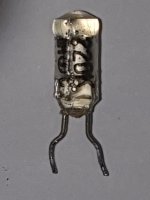
Decided to start at the 22pF and think I got lucky since it turned into a 12ohm resistor on the bench.
Faults don't come much more definite than that 👍
I'm surprised to see a polystyrene type though as they are usually reliable. Wonder if it got damaged when soldered. You will find that type quite expensive these days unfortunately.
'If its hissy and noisy and altering all the time them perhaps a cap. Small compressed disc ceramics are favourites.'Absolutely not 😉 we don't give up that easily.
Thinking aloud, you have +24 or so volts at the output which is correctly turning Q203 on and raising the emitter to 24
Q201 has the correct 14 volts on its base, it has 24 on the emitter and so should be OFF (it should never get that far off 🙂)
A quick and dirty check... if you remove Q201 does the output voltage then swing hard towards ground from its present 24 volts.
There are a few possibilities here. It could be a passive component such as the 22pF cap leaky, also the 1500pF cap or also the two PNP's Q207 and 209.
If its hissy and noisy and altering all the time them perhaps a cap. Small compressed disc ceramics are favourites.
All good. Just keep the volume on minimum.
could you use a poly film cap in place of these?
This is polystyrene and it has clearly been fried by a soldering iron. Replace with same. I deal with these 60+ years old and they do not otherwise fail.
Couldn't find like for like on the web and HiFiCollective had several suppliers for polystyrene capacitors. Asked their advice and they suggested Charcroft Silver Mica. Seemed rather expensive at £5 each so maybe overkill on this class of amp, perhaps I should have asked for recommendations here first. Still, order has gone in now so too late!
As to the frying with a soldering iron, the MM input has never worked during my ownership and I bought the unit second hand. To me that says it was damaged during manufacture and henced failed prematurely. I might have cooked it taking it out but since removal appears to have got the rail down to the correct voltage and I haven't changed anything else I plead not guilty.
My removal technique is heat the solder on the underside and remove with a solder sucker, gently wiggle and pull component applying further heat as necessary. I have lifted enough pcb strips on other repair attempts to be as sparing with heat as possible. Self taught, critique away!😱
- Home
- Amplifiers
- Solid State
- Audiolab 8000A phono stage not working