In the diagram I posted, you should only expect to see clean audio up to the terminal of R26 that is connected to C23.
Is audio clean up to that point in every channel?
Beyond that, up to the speaker terminals, you're in the feedback loop and the signal doesn't have to look clean to be OK.
Is audio clean up to that point in every channel?
Beyond that, up to the speaker terminals, you're in the feedback loop and the signal doesn't have to look clean to be OK.
I checked the signal with the tracer. I will use the oscillioscope . On both channels, it sound ok. The ressitor is in series with a capacitor, connected to pin 7 of the op amp.
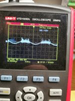
If i check with oscilloscope, i dont get a clean signal anywhere. Always the upper half of the waveform is disorted.
as soon as i disconnect the load from the speaker output, i have a clean, good signal. Connect the dummy load 4Ohm to the speaker terminal, it disorts aggain.
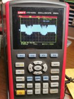
OtherThat's a picture from the other channel in the same time, no load, no input at this channel. Load and input on the other channel.
picture is without load, the other channel is clean.
Attachments
the bias dont have any effect. The current rise or drop when turning the pot, but the signal is always the same.
How it could be, that booth channels show symptons, when only one channel is fed. And only under load.
How it could be, that booth channels show symptons, when only one channel is fed. And only under load.
Iam not shure if iam wrong. I checked again the voltage from the bias op amp. If i use secondary center for ground, i have at pin 4 3V and Pin 8 3.2V.
I have two Zener with 6.2V. Each has 6,2V across. So maybe the something is wrong with the positive Side, and the op amp should have 12.4V Across pin 4 and 8...
I have two Zener with 6.2V. Each has 6,2V across. So maybe the something is wrong with the positive Side, and the op amp should have 12.4V Across pin 4 and 8...
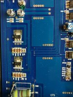
The left Zener produce the voltage for the pre amp circuit. About 32V , 16V per Zener
The right Zener are for bias .I measure across each Zener 6.2V. .. So maybe there is my problem. The diagram i have from the other amp, doesnt fit to this amp..
The right Zener are for bias .I measure across each Zener 6.2V. .. So maybe there is my problem. The diagram i have from the other amp, doesnt fit to this amp..
Attachments
Last edited:
Compare the voltage on the terminals of the two transistors that supply that op-amp to the terminal voltages of the corresponding transistors in the other channels.
Ok, there is something wrong. If i ground my dmm on secondary, and measure the positve resistor i have about 4V, if i want to measure the negative, it shows shortly about 6v and then the amp goes in protect.
Measured on the transistors Emitter BH-16, AH-16 its 3,4 and 3,2V. Both channels the same
Between Emitter and Base 0,6V. so the transistors seems ok.
Between Emitter and Base 0,6V. so the transistors seems ok.
Last edited:
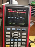
so, here is the problem. the voltage, measured on the left diode, is 6.5V.
if i measure on the cathode, which is connected over a resistor to the transistor, the amp imidiately goes in protect.
The right diode shows 6,5v and 4V, so maybe something is pulling the voltage down.
if i measure on the cathode, which is connected over a resistor to the transistor, the amp imidiately goes in protect.
The right diode shows 6,5v and 4V, so maybe something is pulling the voltage down.
Attachments
can i lift the base from the transistors, which are feeding the op amp, or will it damage something?
if i measure the resistance between pin 4 and 8, first op amp has about 19kohm, the second has 3,6kohm... so which one maybe defective, and can i take a tl072?
- Home
- General Interest
- Car Audio
- Audio System X-Ion 280.2