You can technically run those analysis with AP, but I do agree the frequency limitation compared to a VA is large. Since I don’t understand what information, in the audio range, having let’s say 10MHz BW , can offer,but your observation made me thinking.
Do yoi have an outstanding example that shaped your thinking in this?
Do yoi have an outstanding example that shaped your thinking in this?
The network analyzer is great for measuring impedances, power supply stability, antennas, crystals ... mine is in constant use. There are DIY versions seen in the ham-radio magazines which can be adapted for all the above.
Network analyzers aren't great for sniffing out high frequency signals generated by oscillating amplifiers and so forth. That's not what they're designed for. But, for making impedance and loss measurements, they are what you want.
This one works great for me. There are other variations out there with pluses and minuses.
NanoVNA V2
For finding instabilities and other rogue signals, you want a spectrum analyzer. Like this one:
tinySA
These also can double as high frequency signal generators, too.
Both of the above really start functioning above the usual audio band, beyond where normal audio test systems fall off. Like 50-100 KHz. Although we're really concerned about audio performance, things that happen above the audio band do have an effect on audio performance. For example, most amplifiers that have stability issues have those problems above the audio range. If your preamp is producing a rail to rail signal at 823 KHz due to instability, you won't hear the 823 KHz yourself, but don't you think that'll affect performance below 20 KHz? How about when it mixes with the turn off oscillation of an undamped solid state rectifier at 810 KHz?
I yet have to get an answer on what is that you cannot do with AP used as network analyzer beside the limited bw? 🤔 also stability can be seen with an oscilloscope with decent BW for example I have 400MHz hi end scope and I can see if the output presents oscillation within the BW of the instrument. I personally don’t want to resort to using the RF spectrum anslyzer and the antenna for sniffing to check out an audio circuit which I believe it’s DC to 3GHz lol …but maybe I am missing the importance of doing that. Do you have any practice example where you absolutely needed to look into the hundreds of MHz to resolve an audio circuit?The network analyzer is great for measuring impedances, power supply stability, antennas, crystals ... mine is in constant use. There are DIY versions seen in the ham-radio magazines which can be adapted for all the above.
I am asking to learn other ones’s personal experience.
Well, for one thing, to measure phase accurately with an AP you need several milliVolts of signal. With a VNA you can do it with uVolts.
Here's an example of looking at power supply stability with a VNA. The red line is impedance, the blue line is "Q".
Here's an example of looking at power supply stability with a VNA. The red line is impedance, the blue line is "Q".
Attachments

Do you have any practice example where you absolutely needed to look into the hundreds of MHz to resolve an audio circuit?
I am asking to learn other ones’s personal experience.
Not hundreds. How about 3 MHz? I had a preamplifier that showed a low level oscillation at that frequency.
Yeah, you could probably see it on a regular scope. But, it was easier to find with a spectrum analyzer. Besides, I've found that it's good to be thorough. Back in the days of analog video, I had an opamp circuit be unstable with the instability showing at about 60 MHz. Outside the video range, but that instability did affect the video performance. This is with an opamp that was sometimes used for audio circuits. More recent opamps are often higher bandwidth.
However, I would never try to tell somebody his business or how to go about his hobby.
Yes I do have 10Hz-3GHz Keysight spectrum analyzer. As you mentioned you could see the trace with the scope the analyzer can point well which frequencies are present.
High frequency oscilaltion might and will worsen your THD performance in the audio band or have an improper DC offset behavior.
It seems some folks here have more experience than me using successfully RF tools to improve audio equipment.
I also want to highlight that I like to hear other designers experience that is why I asked examples.
I don’t fully grasp the need to analyze the quality factory of a linear supply for audio design but I will let these comment simmer and start firing up my RF Spectrum analyzer to evaluate if my latest design suffers from very high frequency oscillation.
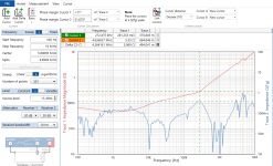
Just unrelated with the latest conversation, but I was running a self-test on my AP and it fails one channel on the CMTST setting on one of the channels.
Not sure why, it passes all the other tests in with this gen configuration. Here the results. Does it mean I have a problem with one isolation transformer on one of the two channels?

Not sure why, it passes all the other tests in with this gen configuration. Here the results. Does it mean I have a problem with one isolation transformer on one of the two channels?
I would verify the source output impedance before suspecting the transformer.
Does the problem move to the other channel if you swap the cables at the source?
Tom
Does the problem move to the other channel if you swap the cables at the source?
Tom
It passes the test at 5 and 10V but fails at 2V and only one channel. If I understand correctly, you are suggesting to swap channels to see if the problem follows. Thanks it’s a great idea. I will do that tonight as soon as I get back home, I just took a break from work to go to the LA Italian festival lol
I have swapped channels i.e. gen out A gois to IN B, while gen out B goes to IN A, the problem doesn't follow, which would suggest the issue is at the input of the analyzer. What can it be?I would verify the source output impedance before suspecting the transformer.
Does the problem move to the other channel if you swap the cables at the source?
Tom
you have the Bode 100, nice Vector analyzer. Can I understand how much this measurement really impacts the design of an audio linear supply?Well, for one thing, to measure phase accurately with an AP you need several milliVolts of signal. With a VNA you can do it with uVolts.
Here's an example of looking at power supply stability with a VNA. The red line is impedance, the blue line is "Q".
I quite don't get it why going to this range and I Am not saying this is not good measurement, rather the opposite I am impressed, I am just trying to understand what this can bring to the table when it comes to an audio gear. Granted we can see stability issue without special insight through a scope.
BTW in the meantime I brought out the spare HP spectrum analyzer 9KHz-1.8GHz to plot the output of the circuit, so I can learn to incorporate more into the daily routine those tools I use for RF design into Audio as well.
For example, if you are using high speed opamps etc (>50MHz) you want to make sure supply impedance is flat (ohmic) and low at all frequencies.Can I understand how much this measurement really impacts the design of an audio linear supply?
I quite don't get it why going to this range and I Am not saying this is not good measurement, rather the opposite I am impressed, I am just trying to understand what this can bring to the table when it comes to an audio gear. Granted we can see stability issue without special insight through a scope.
And when you work on a DAC chip that pulls supply currents at MHz freqs and harmonics and you happen to have an impedance peak at just this frequency you know why distortion is worse than expected. Typical scenario would be the dreaded CLC resonance tank circuit, like paralleling a more remote ceramic bypass cap with a smaller ceramic one closer at the chip, maybe even connected with a long but narrrow trace. Without an impedance analyzer you are sitting completely in the dark here.
Therefore, a network&spectrum analyser vs o'scope offers a similiar level of improvement in observable circuit behavior than a scope does vs. a multimeter.
Also, you have a RF generator that you can use to see if the circuit is prone to EMI.
You can make an LM317 oscillate. Tweaks to LM337 easily decay into oscillation.you have the Bode 100, nice Vector analyzer. Can I understand how much this measurement really impacts the design of an audio linear supply?
I really like my HP3577a but find it's a beast. It was very inexpensive and in cal when purchased. In its virginal state not really suitable for power supplies, but great for crystal filters, component analysis etc
Very true.Typical scenario would be the dreaded CLC resonance tank circuit, like paralleling a more remote ceramic bypass cap with a smaller ceramic one closer at the chip, maybe even connected with a long but narrrow trace. Without an impedance analyzer you are sitting completely in the dark here.
Therefore, a network&spectrum analyser vs o'scope offers a similiar level of improvement in observable circuit behavior than a scope does vs. a multimeter.
Many (most?) power distribution schemes on pcb's these days have resonant peaks all over the place. I think this is because dogma from decades ago about paralleling bypass caps and so on still is commonly applied today.
Despite efforts from people like Howard Johnson to explain all of this, it's hard to move a lot of engineers off their current practices. Beginners don't learn about this until they are on the job, even though they certainly have studied the underlying fundamentals along the way. Many more senior engineers have gone into management roles and expect the people they supervise to follow what they did back when they were practicing engineers.
It's too bad, too. You can simulate a lot of these factors in Spice, and LTspice is free to use. You can also measure a lot of this with low cost VNAs, as you explained. You can design goodness into the pcb or at least allow for a few RC dampers in various places so that you can add them experimentally later. But, none of that seems like it's common practice. Thus, a lot of products don't meet their potential. That's true for DIY efforts as well as commercial offerings. I guess people would rather argue and rationalize...
What is the difference between body 100 and the HO3577a why can’t you use it for power supplies?You can make an LM317 oscillate. Tweaks to LM337 easily decay into oscillation.
I really like my HP3577a but find it's a beast. It was very inexpensive and in cal when purchased. In its virginal state not really suitable for power supplies, but great for crystal filters, component analysis etc
This makes total sense. Usually instabilities at high frequencies due to supply oscillations at one peak frequency can cause degrade in distortion performance. So you can see the effect with audio analyzer but it’s shooting in the darkness to fix it without a network analyzer to determine the proper resonant frequency filter. Bare in mind oscilaltions 8/10 are sue to suboptimal layout. Most designers just choose to go with a solid ground plane as it takes one second to generate and leads to degrade of performance that they try to cure by slowing down the circuit.
Anyone has any idea what could be wrong with this test?Just unrelated with the latest conversation, but I was running a self-test on my AP and it fails one channel on the CMTST setting on one of the channels.
Not sure why, it passes all the other tests in with this gen configuration. Here the results. Does it mean I have a problem with one isolation transformer on one of the two channels?
View attachment 1364471
You probably know already, but just in case: Be really careful with DC and spectrum analyzers. Applying even relatively small amounts of DC to a SpecAn input is a surefire way to wreck the input. Always use a DC block until you're sure that only AC gets to the analyzer. Of course, DC blocks make it harder to measure stuff near DC...Yes I do have 10Hz-3GHz Keysight spectrum analyzer.
Tom
- Home
- Design & Build
- Equipment & Tools
- Audio Precision SYS2522