Horizontal, 40 off axis. I'll see if I can tilt the reponse anti clockwise 1.5deg without introducing too many ripples.

I would suggest to wait for the enclosure simulation - quite a lot will change. It doesn't have to be that resource demanding on the HW, as it can be split into several frequency bands with different mesh densities, etc. And it's the low and midrange frequencies that will change the most.
"96db/watt speakers to run off of solar cells or the acid from pineapples" - @LineSource << huge inspiration.
@mabat it will be interesting to model the transition between cabinet bodies and how a radius or gap affects diffraction. Such as below - 30mm rad on both boxes or continuation of vertical shape downward.
Could ATH specify multiple bodies like https://www.diyaudio.com/community/...-design-the-easy-way-ath4.338806/post-6977513 ?
Last edited:
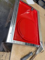

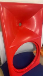
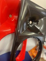
Popped!Just gel coat, tissue and 2 lams of 450g.
Attachments
; -------------------------------------------------------
; Enclosure Setting
; -------------------------------------------------------
Mesh.Enclosure = {
Spacing = 31,31,31,346
Depth = 250
EdgeRadius = 28
EdgeType = 1
FrontResolution = 8,8,16,16
BackResolution = 20,20,20,20
}
; -------------------------------------------------------
; Mesh Setting
; -------------------------------------------------------
Mesh.LengthSegments = 20
Mesh.AngularSegments = 120
Mesh.ThroatResolution = 2.0
Mesh.MouthResolution = 10.0
Mesh.CornerSegments = 8
Mesh.Quadrants = 14 ; 1/2 symmetry
Mesh.SubdomainSlices =
Mesh.ZMapPoints = 0.5,0.1,0.76,0.733
; -------------------------------------------------------
; ABEC Project Setting
; -------------------------------------------------------
ABEC.SimType = 2
ABEC.Abscissa = 1 ; 1=log | 2=linear
ABEC.f1 = 200 ; [Hz]
ABEC.f2 = 20000 ; [Hz]
ABEC.MeshFrequency = 1000
ABEC.NumFrequencies = 100
ABEC.Polars:SPL_H_norm = {
MapAngleRange = 0,90,19
NormAngle = 10
Distance = 5
}
ABEC.Polars:SPL_V_norm = {
MapAngleRange = 0,90,19
NormAngle = 10
Distance = 5
Inclination = 90
}
; -------------------------------------------------------
; Output
; -------------------------------------------------------
Report = {
Title = "Limacon Project2-boxed"
Width = 1200
Height = 800
NormAngle = 10
}
Settings above are used for the following outputs. Thanks @fluid for the Mesh.ZMapPoints setting.
Comments welcomed. I will try to complete one this weekend and measure. 🙂
Currently investigating symmetry settings in ATH4 and trying to understand how MapAngleRange works for vertical polar generation and the assymetry (waveguide at the top of the baffle).
Horizontal Data


Vertical Data


Currently investigating symmetry settings in ATH4 and trying to understand how MapAngleRange works for vertical polar generation and the assymetry (waveguide at the top of the baffle).
Horizontal Data
Vertical Data
Last edited:
This translates 1:1 to the ABEC parameter "PolarRange" in its observation script. Related ABEC parameter is the BasePlane=.Currently investigating symmetry settings in ATH4 and trying to understand how MapAngleRange works for vertical polar generation and the assymetry (waveguide at the top of the baffle).
You can change this at will in the "observation.txt" file that Ath generates.
I attached an observation script to look full 360 degrees vertical and 180 degrees horizontal, example code attached, looking to 90 degrees only shows you the edge not beyond, observation scripts can be changed and the new spectra solved without having to resolve the whole modelComments welcomed. I will try to complete one this weekend and measure. 🙂
Currently investigating symmetry settings in ATH4 and trying to understand how MapAngleRange works for vertical polar generation and the assymetry (waveguide at the top of the baffle).
Code:
BE_Spectrum
  PlotType=Polar; GraphHeader="V Polar Down"
  PolarRange=0,180,37
  Farfield=true; BasePlane=zy
  Distance=2m
  //Offset=200mm
  //NormalizingAngle=10
  502  Inclination=0  ID=5002

BE_Spectrum
  PlotType=Polar; GraphHeader="V Polar Up"
  PolarRange=0,180,37
  Farfield=true; BasePlane=zy
  Distance=2m
  //Offset=200mm
  //NormalizingAngle=10
  503  Inclination=180  ID=5003
Attachments
Just a remark - you seem to combine Farfield=true and Distance=2m - these two should be exclusive, use either Farfield or a specific distance.
(If you don't specify a Distance in the Ath script, far-field data will be calculated, i.e polars "very far" from the source with level adjusted to 1m with phase corrected for the travel distance I think. I've got used to use this, i.e. omit the Distance item.)
(If you don't specify a Distance in the Ath script, far-field data will be calculated, i.e polars "very far" from the source with level adjusted to 1m with phase corrected for the travel distance I think. I've got used to use this, i.e. omit the Distance item.)
True, I often keep things in and comment them out but in this case it would be farfield as the distance is ignored
"Farfield=
Farfield=true or simply Farfield performs the sound pressure calculation at a large distance. Parameter Distance= is ignored.
If Farfield=true then the amplitude gets internally normalized to a distance=1m and the phase at distance=0 (ie normalized to the point of rotation of the observation arc)."
Hello fluid,I attached an observation script to look full 360 degrees vertical and 180 degrees horizontal, example code attached, looking to 90 degrees only shows you the edge not beyond, observation scripts can be changed and the new spectra solved without having to resolve the whole model
Code:BE_Spectrum PlotType=Polar; GraphHeader="V Polar Down" PolarRange=0,180,37 Farfield=true; BasePlane=zy Distance=2m //Offset=200mm //NormalizingAngle=10 502 Inclination=0 ID=5002 BE_Spectrum PlotType=Polar; GraphHeader="V Polar Up" PolarRange=0,180,37 Farfield=true; BasePlane=zy Distance=2m //Offset=200mm //NormalizingAngle=10 503 Inclination=180 ID=5003
you set Inclination to 0 and 180 degree for verticals. Is there a secret, or am I right that this will produce horizontal read outs? Zero to my understanding is 3 o'clock horizontal plane, 180 degree is opposite side, still horizontal.
- Home
- Loudspeakers
- Multi-Way
- ATH4 waveguide inspired multi way