Babowana said:
Missing diyAudio and good members. . . would visit more
frequently? Hmm. . . it seems that the life is not that easy. . .
After having got the acceptance to leave the hospital, last week
I could come back home. And, took the attached photo. . .
(ah? oh. . . lung cancer. . . actually small cell cancers near by the
lung. I needed just chemotherapy treatment, not anything else)
It seems that I have very luckily saved my life. . .
So, I am now planning a small diy audio project. . .
And, I am thinking to donate a small amount to diyAudio through Pass Labs forum. . . I have learned many many good things through, particularly, Pass Labs forum. . .
Cheers!
JHY
🙂
We would like to wish a quick recovery Babo. Keep contributing your ideas in this forum.
Babowana-
Welcome back! May you have a speedy recovery!
I will look forward to the amp project!
JJ
Welcome back! May you have a speedy recovery!
I will look forward to the amp project!
JJ
Thanks, friends!!!
Thanks to you, I'm really getting better. I feel this movement daily.
Reference: the Sketch posted #122
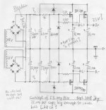
As I do not receive any comment from you, I like to go with this PSU for my new F5. The reasons are as follows:
1. I like to use the 2nd-hand 2x25VAC 500VA EI-transformer. With this PSU, I could cut off the rail voltages down to abt +/-25V and, at the same time, I could have better voltage regulation.
2. One PSU could cover both channels, saving four psu caps of 33,000uF or slightly smaller ( the size would depend on the availability in the shop).
3. This PSU does slow satrt (with 1k and 2,200uF).
4. This PSU has a bleeder (of 2.2K3W) that could drain the heavy caps in short time when the amp is turned off.
I have just finished my plan of PCB for the PSU, waiting for my 3rd chemotherapy treatment injections. I wil post the Sketch of this PCB one week after the 3rd treatment. . . 🙂
Cheers,
Thanks to you, I'm really getting better. I feel this movement daily.
Reference: the Sketch posted #122
As I do not receive any comment from you, I like to go with this PSU for my new F5. The reasons are as follows:
1. I like to use the 2nd-hand 2x25VAC 500VA EI-transformer. With this PSU, I could cut off the rail voltages down to abt +/-25V and, at the same time, I could have better voltage regulation.
2. One PSU could cover both channels, saving four psu caps of 33,000uF or slightly smaller ( the size would depend on the availability in the shop).
3. This PSU does slow satrt (with 1k and 2,200uF).
4. This PSU has a bleeder (of 2.2K3W) that could drain the heavy caps in short time when the amp is turned off.
I have just finished my plan of PCB for the PSU, waiting for my 3rd chemotherapy treatment injections. I wil post the Sketch of this PCB one week after the 3rd treatment. . . 🙂
Cheers,
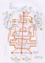
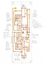
Here you are.
My F5 PSU PCB is quality of a hobby-grade, not commercial-grade.
As this is a DIY, I just made for my own DIY, without thinking about any beuty too much on it. . .
The pcb shows six jumper wires marked with dot line. . .
Any comment? Thanks 🙂
My F5 PSU PCB is quality of a hobby-grade, not commercial-grade.
As this is a DIY, I just made for my own DIY, without thinking about any beuty too much on it. . .
The pcb shows six jumper wires marked with dot line. . .
Any comment? Thanks 🙂
Attachments
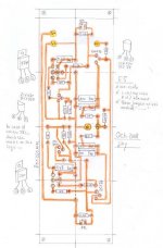
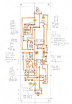
My F5 AMP PCB is also a quality of a hobby-grade. . .
including three jumper wires. . .
Few of diyers dislike the jumpers. But, for me they are OK because
they are just the same as resistors of almost zero ohm, which are
arranged on the pcb as many other resistors.
The NTC is arranged near to the drain pins of the MOSFETs. . .
Any comment?
No comment is the best comment, but not always. . .
🙂
Attachments
Babo-
That's a very neat layout. It looks much better than mine, which was wired point to point and looks atrocious.
I am sure it will sound great. But will it sound different than the Babo Zen 5?
JJ
That's a very neat layout. It looks much better than mine, which was wired point to point and looks atrocious.
I am sure it will sound great. But will it sound different than the Babo Zen 5?
JJ
Babowana said:....
No comment is the best comment, but not always. . .
🙂
local decoupling PSU caps ?
you can also cut that V- trace , and left it on bottom of drawing (pcb) , so you'll have V- down and V+ up
Very Nice
I have been waiting for a while to make this amp but no boards. Your doing far better than I could ever dream of doing.
Comment:
Down the bottom, where your 'link' comes from the V- rail, maybe you could make this junction your main input point for the v- supply(and remove the other rail running up the back).
Then go directly up from this point following the line of the 'link' to where your v+ joins onto the v+ rail, that 'T' junction. Maybe make this your main v+ supply point. You would have to make a 'link' underneath, that would come up to those two resistors though, like you have for the V- rail at the bottom.
That will still look neat as the v- & v+ will be inline, but opposite. Then you will have some space on the side of the board that could be cut down so the FET's could be closer the edge. and easier to mount......
Does that make sense?
Maybe not a good idea, I have never made a board up so ignore this if it all sounds stupid.
Regards
Brett.
Sorry.....been beat'n to it..
And
What about cutting that track running on the other side. Just make a trace running directly up to the (1K?) next to the 2SK170. Then where the 100K(?) going to ground is, make a "link down to the other side of the 2SJ74. That would also cut some width off........ sound o.k?
What about cutting that track running on the other side. Just make a trace running directly up to the (1K?) next to the 2SK170. Then where the 100K(?) going to ground is, make a "link down to the other side of the 2SJ74. That would also cut some width off........ sound o.k?
Zen Mod said:local decoupling PSU caps ?
you can also cut that V- trace , and left it on bottom of drawing (pcb) , so you'll have V- down and V+ up
Are you referring to PSU or AMP PCB? I guess that you are referring to AMP PCB.
Please note that I'm using one-sided PCB, not double-sided. . .
Anyway, I see your point. Thanks for the input!
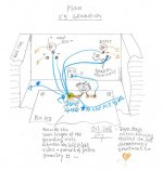
By the way, I'm attaching another sketch showing the connection
points between the PSU board and the neighbouring components. . .
🙂
Attachments
jupiterjune said:... But will it sound different than the Babo Zen 5?
I do not expect different sounds. . .
I'm just trying to make my audio-diy move on with something available. . .
Otherwise, I feel myself boring. . .
🙂
Re: And
Sounds stu. . .? No, no.
You have good and valid points. . .
I will change some part(s) of AMP PCB based on your comments. . .
By the way, I will arrage the MOSFETs and the AMP PCB vertically
as shown in the attached drawing.
Cheers,
JHY
🙂
enzedone said:Comment:
Down the bottom, where your 'link' comes from the V- rail, maybe you could make this junction your main input point for the v- supply(and remove the other rail running up the back).
Then go directly up from this point following the line of the 'link' to where your v+ joins onto the v+ rail, that 'T' junction. Maybe make this your main v+ supply point. You would have to make a 'link' underneath, that would come up to those two resistors though, like you have for the V- rail at the bottom.
That will still look neat as the v- & v+ will be inline, but opposite. Then you will have some space on the side of the board that could be cut down so the FET's could be closer the edge. and easier to mount......
Does that make sense?
Maybe not a good idea, I have never made a board up so ignore this if it all sounds stupid.
enzedone said:What about cutting that track running on the other side. Just make a trace running directly up to the (1K?) next to the 2SK170. Then where the 100K(?) going to ground is, make a "link down to the other side of the 2SJ74. That would also cut some width off........ sound o.k?
Sounds stu. . .? No, no.
You have good and valid points. . .
I will change some part(s) of AMP PCB based on your comments. . .
By the way, I will arrage the MOSFETs and the AMP PCB vertically
as shown in the attached drawing.
Cheers,
JHY
🙂
Attachments
Is your design using the same parts from the schematic posted by Mr Pass?
I would like to use something similar.
I would have to have a board lying vertical due to lack of space I'll have.
Brett.
I would like to use something similar.
I would have to have a board lying vertical due to lack of space I'll have.
Brett.
enzedone said:Is your design using the same parts from the schematic posted by Mr Pass?
Brett.
Yes, the same.
Here I attach Rev 01 of F5 - AMP pcb. . . 🙂
Attachments
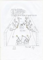
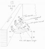
Ok! Here is my plan of grounding for F5. . .
This method has well worked for me. . .
Now I'm ready to build (or re-newal) the F5 as designed by Papa.
But, it seems that I have to wait for a certain time as I'm still in
the middle of the chemotherapy treatments. . . Mmm. . .

This method has well worked for me. . .
Now I'm ready to build (or re-newal) the F5 as designed by Papa.
But, it seems that I have to wait for a certain time as I'm still in
the middle of the chemotherapy treatments. . . Mmm. . .
Attachments
- Status
- Not open for further replies.
- Home
- Amplifiers
- Pass Labs
- ATC SCM7 . . . with Papa's diy amp?